Hiya,
I have a Nak ST-7 here that has no display at all.
All else works fine.
Was hopeing someone here either has a schematic or can point me to the fault.
Thanks....
I have a Nak ST-7 here that has no display at all.
All else works fine.
Was hopeing someone here either has a schematic or can point me to the fault.
Thanks....
Nice tuner
Hi MadMutt,
Sorry, that's one I don't have yet.
The fault should be easy to troubleshoot.
Firstly, does it work otherwise? If so ....
Look for bad solder connections.
-Chris
Hi MadMutt,
Sorry, that's one I don't have yet.
The fault should be easy to troubleshoot.
Firstly, does it work otherwise? If so ....
Look for bad solder connections.
-Chris
Yup, otherwise it works 100%
Ta, shall pull the main board (oh what fun) and start a joint hunt.
Sounds like you think is a common problem ?
Are there others I should be tending to while I'm at it ?
Ta, shall pull the main board (oh what fun) and start a joint hunt.
Sounds like you think is a common problem ?
Are there others I should be tending to while I'm at it ?
Hi MadMutt,
Change the memory battery (or capacitor). I can't remember which it is. There was a service note to change the diode to the memory battery (or capacitor) to a schottky type to prevent memory loss at start up. The details escape me, but it was a "do to all" type campaign to get all of them no matter why they came in for service. Your's is probably fine.
I can not recall wether this was an LED type, or an FL display. If you see a glass tube, it's an FL display. Often with FL types, either the heater connections become intermittent or open (craked connections), or the (approximately -30 VDC) supply fails. It is regulated and can be anywhere from 20 to 35 VDC. Normally negative unless they switch the positive when driving the digits.
I doubt it's an LED display because you are more apt to lose segments rather than the entire display.
Another thought is this unit may have an AC fail circuit that mutes the display. Normally a small glass diode charging a 1 uF capacitor in the power supply. If I had the diagram I could tell you.
-Chris
Excellent, ta for the pointers.
Memory is a cap, display is Fl.
Transformer has 3 tappings - 30vac - 15vac - 3.3vac this one has a gnd (?) with it
Memory is a cap, display is Fl.
Transformer has 3 tappings - 30vac - 15vac - 3.3vac this one has a gnd (?) with it
Hi MadMutt,
Normally the 3.3 VAC tap is biased to - 20 ~ 30 VDC -ish. The regulators often go open. Either the digit pins will have a + supply or the heaters will be tied to a - supply with the segments going to + 5 VDC.
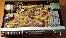
Measure around the power supply with your meter. Can you please post a photo of the power supply area?
-Chris
Great! Replace that cap. 5.5 VDC unit, right?Memory is a cap, display is Fl.
Wish I had the manual.Transformer has 3 tappings - 30vac - 15vac - 3.3vac this one has a gnd (?) with it
Normally the 3.3 VAC tap is biased to - 20 ~ 30 VDC -ish. The regulators often go open. Either the digit pins will have a + supply or the heaters will be tied to a - supply with the segments going to + 5 VDC.
Measure around the power supply with your meter. Can you please post a photo of the power supply area?
-Chris

Ohh, should also add, I have a 'spare but not' st7 here for comparison purposes.
After a bit of playing around (not easy to pull apart in some areas), I think I've narrowed down the fault to the actual display board.
When I use the display board from the 'not spare' unit, it works fine.
Guess that means the vfl is shot.
Don't spose there's any hope of replacements out there ?
After a bit of playing around (not easy to pull apart in some areas), I think I've narrowed down the fault to the actual display board.
When I use the display board from the 'not spare' unit, it works fine.
Guess that means the vfl is shot.
Don't spose there's any hope of replacements out there ?
Hi MadMutt,
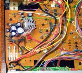
See all that dark brown "glue"? Remove it. It can go conductive and corrosive.
-Chris
See all that dark brown "glue"? Remove it. It can go conductive and corrosive.
No, not unless the filament is open. Check for your voltages (compare). Check the display uP is running (need 'scope). It might be fine once you clean it up.Guess that means the vfl is shot.
-Chris
Only gorilla snot I see is on the back of the display board. (cable anchoring)
I shall remove it.
Will post back when done and tried.
Any idea which pins on the display are the heaters ?
Wondering if I can check the actual display.
Only hiccup is that the two ST-7's I have are ever so slightly different in wiring.
Good display in bad unit = good.
Bad display in good unit = bad.
So the fault follows the board.
Might even swap the main i.c over as an acid test.
If I get crazy I could even swap the vfd over, but I'm hesitant as I don't want to damage the good one.
Oh, I do have a scope too.
Hi MadMutt,
The two pins on the outside are generally the filaments. Often two are shorted together on each end, look at the leads. If you unplug the board, compare the resistance between those two points on both boards.
-Chris
The two pins on the outside are generally the filaments. Often two are shorted together on each end, look at the leads. If you unplug the board, compare the resistance between those two points on both boards.
-Chris
Compare with other board.
Yes.
I'm obviously having a 'blonde' day. 🙄
So obvious yet . . . . . .
Yes.
I'm obviously having a 'blonde' day. 🙄
So obvious yet . . . . . .
- Status
- Not open for further replies.
- Home
- Source & Line
- Analogue Source
- Nak ST-7 circuits or repair info please