Hi folks,
I'm an happy owner of this 2x5881 PP and I'm asking myself looking at the schematics about the phase inverter part of the circuit.
As I see it, it looks like a long tail pair circuit, but I don't get how the gain is leveled between the 2 outputs.
Most of the time, the gain difference is leveled via plate resistors, but there are the same, and there is this weird thing going to the grid of the second tube.
Please light me up on this !
Cheers
Attachments
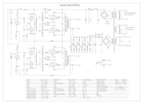
It is indeed an ordinary long taled pair. The only difference is the input grid gets its DC reference directly from the preceding stage anode -it is DC coupled. The second grid is decoupled to ground as normal. A very common arrangement, e.g. Mullard 5-20.


The gain is not leveled. The NFB takes care of (most) inbalanceHi folks,
I'm an happy owner of this 2x5881 PP and I'm asking myself looking at the schematics about the phase inverter part of the circuit.
As I see it, it looks like a long tail pair circuit, but I don't get how the gain is leveled between the 2 outputs.
Most of the time, the gain difference is leveled via plate resistors, but there are the same, and there is this weird thing going to the grid of the second tube.
Please light me up on this !
Cheers
As the cathode voltage is very large, the cathode resistor must also be large, so the gain differential is very small, so the required plate resistor difference is also very small. Millard 5-20 also exhibits this. A useful side benefit of setting up the stage for DC coupling inbound.
Three philosophies:
Use negative feedback to fix errors in the amplifier signal path.
Not balancing the plate signal amplitudes is an example of this.
Perhaps 40% of amplifiers do it this way.
This is the simplest to design.
Use intrinsically lower errors in the amplifier signal path, which allows for less negative feedback.
Balancing the plate signal amplitudes by adjusting the resitances of the phase inverter is an example of this.
Perhaps 40% of amplifiers do it this way.
This requires calculations to determine the plate load resistances.
Use a true current source (sink) instead of the cathode resistor; and use precision matched plate loads. Less negative feedback required.
Perhaps 20% of amplifiers do it this way.
That is the method that I use, but it is my preference.
If there is no negative supply voltate for the current source, it can require some calculation, like burden voltage of the current source, bias voltage of the tubes, and voltage levels versus signal swing.
Very instructive reading.
With my naive standpoint right now, I assume that the amount of reverse feedback tells about the design (and sound ?) quality of an amp ?
I've tried some mods on guitar amps playing with this reverse feedback value, where is often the presence control. Even tried to remove completly, with poor results, muddy sound.
- Home
- Amplifiers
- Tubes / Valves
- (naïve) Question about this phase inverter circuit