I've recapped a nice old Nad 3020, this has been a fast and simple job (and I had a huge improvement in sound quality).
Now I would like to
1. replace diodes with some Schottky, but I don't understand wich ones I have to use;
2. bypass tone controls: can I just connect the volume output pot to the power amp input?. I've found more complex ways to do this mod on the web but as I don't have a great electronic know how I fear to damage the device.
Thanks in advance for any help.
Now I would like to
1. replace diodes with some Schottky, but I don't understand wich ones I have to use;
2. bypass tone controls: can I just connect the volume output pot to the power amp input?. I've found more complex ways to do this mod on the web but as I don't have a great electronic know how
I fear to damage the device.Thanks in advance for any help.
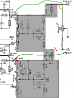
This is the modification
I would do in PRE OUT.
Red = Cut trace
Green = New Trace
As you can see you have 2 output Caps from pre:
C517 and C518. These are electrolytic 47 uF.
I would change those to FILM CAPS of better quality,
MKT Polyester or Polypropylene (a bit more expensive and larger).
I would go for value 4.7 uF or 10 uF.
( 2 x 4.7uF in parallell = 9.4 uF )
This is if you want to keep the balance POT function.
This is a linear 20 kOhm potentiometer.
!0 kOhm to each side, when set in middle.
Attachments
schottky diodes tend to have low PIV ratings. i don't remember what the rail voltages of the 3020 are (it's been a long time since i worked at NAD), but the rule of thumb is that the PIV rating of a rectifier should be more than the peak-to-peak voltage of the AC feeding them. if you have 50V rails (+/- 50), then the PIV rating of the rectifier should be at least 100V, with most manufacturers actually using 200V devices. if you have to stack schottky devices to get a high enough PIV rating for your power supply, you will end up with the same or higher forward voltage drop across the rectifier as you have now with silicon devices.
Thank you Lineup, it seems a very easy job. I'm not interested in balance control so I will disconnect the pot.
Can I solder the wire from C518 directly to power amp input? What the difference between 'normal in' and 'lab in'?
Unclejed613, the original diodes are BAW62, IN60 and IN4002 (this means nothing to me!😕 ).
Can I solder the wire from C518 directly to power amp input? What the difference between 'normal in' and 'lab in'?
Unclejed613, the original diodes are BAW62, IN60 and IN4002 (this means nothing to me!😕 ).
Attachments
Calamaro said:Thank you Lineup, it seems a very easy job.
I'm not interested in balance control so I will disconnect the pot.
Can I solder the wire from C518 directly to power amp input? What the difference between 'normal in' and 'lab in'?
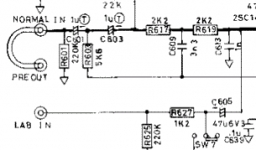
I do not know what 'LAB IN' is for.
Maybe for some testiing purpose ....
I told you you could replace the 47uF cap C518 with 4.7/10uF FILM Cap.
When you do not use either Balance control (10kohm load) or Tone controls,
you can do very well using as small FILM Cap ( MKT or Polypropylene )
as 2.2 uF or even 1 uF 🙂 .
This is because the R601 (220kohm) + the input circuit of Power amp
is a much lighter load, now.
Then the tone control+balance potentiometer
A resistor 220k vs. 10k, is 22 times easier load!
The heavier load the bigger value for C518.
Now 20 times lower than 47uF is ... ~2.2uF.
And to find and buy a good MKT /Polypropylene at 1uF/2.2uF is not too expensive.
And still it will be An Upgrade in quality.
About your question.
You can solder directly from CAP C518 to top of R601 in my attached schematic.
In this case this resistor have value '220 kohm'.
If the wire you need is for this is longer than like 5-10 cm
then you can use a piece of shielded RCA stereo cable
and you solder the shield of this wire to Ground,
but only at one side, the Power Amp side (somewhere close to resistor R601).
Most probably you can do well without using shielded cable.
Just use thin plastic insulated copper wire.
-------------
Generally, for wiring in amplifiers:
It is always good to use as short wire as possible.
But not as short that it is stretched. Like a straight line.
It has to be able to slack a bit .... give after ... some centimeters.
Attachments
Thank you again for your very clear explanation. I did the modification: replaced c518 with some mkp then wired it to power amp input (via a twisted pair from Cat5 that I could replace later). The amp works but tone controls aren't bypassed! Tried again disconnetting c520, but I hear hums. Checked again and... reality differs from schematics  C520 is 100 uF... Googled around, my amp seems more like a 3020a model, no separated power board. I really don't understand 😕
C520 is 100 uF... Googled around, my amp seems more like a 3020a model, no separated power board. I really don't understand 😕- Status
- Not open for further replies.
- Home
- Amplifiers
- Solid State
- Nad's mods