I would like to know how those lamps operates...it seems some new models have two supply voltages and those lamps (one to each channel) ligths when power is high.
I do not have an idea how this is operating and i would like to know.
Can you explain that to me?
My source of schematics is Jan Dupont site... and it is not working those days... reason why i cannot download the schematic to study and understand the operation.
Please... if you really know more than i know about... and this is not difficult as i know nothing or half of nothing about... then please go ahead to explain me.
Yes... i have readed the NAD informations about... i want to understand the logics into this operation... were those lamps are installed, in series?... in paralel?... and in series with what?... in paralel with what?.. supply?.. speaker? ... emitters?... where?.... what kind of job are they doing there?...is this a kind of energy wasting? (resistance in series)... or loading? (resistance in paralel)
Boys...to repeat what was already published into the NAD site will not contribute.... there you have marketing informations, and some basic ideas about the circuit... i would like to understand how it operates electronically or electrically.
Thanks in advance by your kindness
regards,
Carlos
Take a look at this video and you will understand what i mean.
thank you by the attention.
http://www.youtube.com/watch?v=hO58rNwo1g8
regards,
Carlos
thank you by the attention.
http://www.youtube.com/watch?v=hO58rNwo1g8
regards,
Carlos
NAD Electronics call this "power drive-s"
I am wondering the meaning of this "s"... stup..?
ahahahahah!
I am feeling myself stupid not to understanding the idea they had.
http://nadelectronics.com/powerdrive-s
I am wondering the meaning of this "s"... stup..?
ahahahahah!
I am feeling myself stupid not to understanding the idea they had.
http://nadelectronics.com/powerdrive-s
Carlos looks like Nad included some 80s sound to light disco strobes, to improve sales maybe, popular with teenagers all these lights blinking, it goes with the music playing in the background too.
😀 😀 😀
On a more serious note, do you have schematics of this amp??
Thanks for the link the other day, pity they dont have any other values or voltages.
😀 😀 😀
On a more serious note, do you have schematics of this amp??
Thanks for the link the other day, pity they dont have any other values or voltages.
The purpose of the lamps is to cause massive sagging on the (too high) supply rails so that the undersized output stage and heatsink don't melt when high average output power is demanded.
Eva is competent... she use to beat everybody.. and daily
And it is good to have her around.
So.... they are trying to have some dinamics... as during some small peak moments, some audio transients, peaks, will be twice or more than twice (4 times more maybe) the average power.
And during continuous tone the supply drops to a lower level good enougth to allow the output transistors (weak ones) to survive.
The lamps are there, in series with the supply to reduce the voltage when needed...interesting Eva.... this use to produce interesting sound...i had in the past one amplifier that had weak supply... so, during peaks was great..but under load, sinus signal entering the power was small.
thank you.
regards,
Carlos
Homemodder, as i told into the begining of this thread
I use to download (and upload too) schematics from and to Jan Dupont's site.
The site is "out of the air" for a while... "under maintenance"... under repair.
So, i cannot find the schematic... i have not into my hard drive..... my auxiliary hard drive is Jan Dupont's site.
All i had was sent to Jan Dupont.... and all he had into his site i had recorded into my hard drive ... them my hard drive burned and i lost the data,... now i am waiting Dupont's site to be working to download all the stuff once again to this new hard drive.
In some sense i will be his backup and he will be my backup.
regards,
Carlos
Now fully understood...the lamp goes in series into the supply
there are two supplies windings, two voltages, one goes througth the lamp.
This way, low power transformer, transistors, small heatsinks, a 40 watts amplifier, will be able to produce higher power into peaks..small time power.
Nice that.
I am satisfied, not more doubts.... to my needs, the thread already did the job.
thank you folks.... i have received some article, brochure and explanation and now i have a good understanding how this unit operates....to understand more, and deeply, i will be waiting the schematic.
regards,
Carlos
Attachments
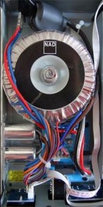
The halogen lamps goes in series with the bigger voltage rails
when the amplifier sucks current from the higher voltage rails, means it is producing more power than it can continuously produce without cook the output transistors..... the current crosses the lamp and the lamp heat up... the starting resistance is 1 ohm...when the lamp goes hot the resistance jumps to 4 to 5 ohms, this will create a voltage drop when the high level signal is constant, protecting the output.
When the peaks are not too much long in time...lamp does nothing... goes in series having 1 ohm, producing small voltage drop.
The lamps, seems to me to be automobile halogen lamps, as they have also 1 to 2 ohms resistance.
The higher voltage supply is 40 percent bigger in voltage compared to the smaller voltage supply..... the smaller may be 32 volts more or less and the bigger may be around 45 volts simetrical.
Interesting...very clever, very interesting...for sure produce the peaks we need, having reduced cost, not needing switching as class H asks for....good.
regards,
Carlos
Carlos,
😀 😀 It's Class G in reverse. You don't want to go there. What it really means is "lets design a 100 watt amp and when it really needs that power lets switch to a low voltage rail"
Now think on this 😉 , if those bulbs had been encapsulated into little light proof boxes with the words " Dynamic interactive PSU" or something, that would really have had us wondering what was in there 🙂

I perceive the design as clever....low price solution giving you some
punch into the peaks... lovely idea i think.
regards,
Carlos
punch into the peaks... lovely idea i think.
regards,
Carlos
Class D can produce more power from just a pair of TO-220 output devices with far less heat wasted and similar THD and complexity. Power supply requirements are half or less.
Yes..for sure... i have one here.. i use to listen
it is amazing how cold it operates... sound is nice...but i am still trying to understand and figure out "were is the sound stage?"
Has none into my system.
But i like it anyway.... it is a non hot and "cool" amplifier.
I do not listen it with those speakers... and mine has nice distance between left and rigth and i use to sit into the correct position.
This one has losses into 25 hertz and do not have good response above 16 kilohertz.
regards,
Carlos
Attachments
Old thread but...
I have read measurements of other nad models and they do give more power at peaks.
If the nad C316 spec sheet says
IHF dynamic power
8 ohms: 90 W
4 ohms: 120 W
2 ohms: 170 W
and the Lamp limits the current when peaks/transients occure. Isnt that contradictory ? When does it starts giving power and at what point limits it ? What is IHF standard ?
thanks and regards.
I have seen this type of protection on BOSE speakers but never in 30 year of repairing gear on an amplifier and I challenge you to show me a schematic from NAD or any other brand with it.
OK. I suppose there may be fixed range when bulbs starts to protect the outputs and circuits. For a moment lets forget protection. As music is complex any measurements where it shows how much the high power the NAD circuits has sustained its high voltage/current supply. I mean duration of peaks and not contineous loud output.
The lamps act as variable resistors in the power supply rails, much like full power rated "lightbulb limiters" or "dim-bulb tester" devices, which have quite a few milliseconds delay as the power dissipated by the amplifier and speakers plus power lost in the light and heat dissipation, reaches a safe plateau.
Essentially, the peak duration you mention, would cause some analogous amount of heat and light in the bulb but whatever type of fast or slow current limiting is used, it must either limit/compress the dynamic signal, blow a fuse or open a relay incredibly fast if it is to prevent damage to those expensive power transistors in the extremes of likely abuse. Unfortunately, there is still no magic electronic circuit that somehow prevents damage without altering the audio in some way. NAD 315BEE and similar amps though, are reputed to be more reliable and easier to live with than most budget amplifiers that have limiting protection.
The better plan though, is not to be riding close to the safe maximum power limit and therefore depending on limiters in any event. If you really need more power and not just supposing that you might need it one day, spend the money and get a much bigger amp. as a priority.
https://www.ecoustics.com/electronics/forum/home-audio/169542.html#:~:text=Dynamic power means what short,duration the signal must be.
This link to another forum, may help explain what the old IHF standard for hi-fi audio power measurement meant and why claims based on it, can seem exaggerated. True or not, it gives some insight into the meaning of power measurements and why manufacturer claims often look suspect.
This link to another forum, may help explain what the old IHF standard for hi-fi audio power measurement meant and why claims based on it, can seem exaggerated. True or not, it gives some insight into the meaning of power measurements and why manufacturer claims often look suspect.
- Home
- Amplifiers
- Solid State
- NAD power lamps inside the enclosure