Hi All,
I'm playing with a faulty NAD C300. One of the MOSFETs died and had blown the 5 amp fuses. I've replaced the MOSFET but before powering up the amp fully, I'm checking the unit for other issues. Looking at the supply voltages on the power supply board (with the amp board disconnected) I'm not getting the rectified voltages I expect - but I'm struggling with a common ground reference. Fwiw I believe the transformer is good. It's windings seem to be correct when each winding is measured to its corresponding CT and pair - for both volts and resistance. This poses me two questions I'd appreciate advice on.
First Question: The circuit diagram in the service manual shows the centre tap of both the secondaries being connected on the power supply board and forming ground - but they're not connected until the amplifier board. I assume it's ok to connect them on the power supply board while testing so I have an easily accessible ground reference since they are connected but by a different part of the circuit? Trying to hold a multimeter probe onto a header pin is asking for trouble...
Second Question: Another deviation from the service manual is that Ground is directly connected to Chassis on the amp board. The service manual shows different types of separation between Ground and Chassis depending on where the connection occurs in the circuit but no direct connection. Is there a reason why the chassis (which has no connection to Mains Earth / Protective Earth) would have been directly connected to circuit ground? Is there any reason I shouldn't reinstate the separation shown in the service manual?
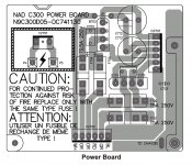
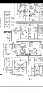
I have attached images showing the power board layout and relevent circuit diagram. All replies gratefully received.
I'm playing with a faulty NAD C300. One of the MOSFETs died and had blown the 5 amp fuses. I've replaced the MOSFET but before powering up the amp fully, I'm checking the unit for other issues. Looking at the supply voltages on the power supply board (with the amp board disconnected) I'm not getting the rectified voltages I expect - but I'm struggling with a common ground reference. Fwiw I believe the transformer is good. It's windings seem to be correct when each winding is measured to its corresponding CT and pair - for both volts and resistance. This poses me two questions I'd appreciate advice on.
First Question: The circuit diagram in the service manual shows the centre tap of both the secondaries being connected on the power supply board and forming ground - but they're not connected until the amplifier board. I assume it's ok to connect them on the power supply board while testing so I have an easily accessible ground reference since they are connected but by a different part of the circuit? Trying to hold a multimeter probe onto a header pin is asking for trouble...
Second Question: Another deviation from the service manual is that Ground is directly connected to Chassis on the amp board. The service manual shows different types of separation between Ground and Chassis depending on where the connection occurs in the circuit but no direct connection. Is there a reason why the chassis (which has no connection to Mains Earth / Protective Earth) would have been directly connected to circuit ground? Is there any reason I shouldn't reinstate the separation shown in the service manual?
I have attached images showing the power board layout and relevent circuit diagram. All replies gratefully received.
Attachments
Circuit and layout differ indeed.
On CZ702 pin 1 and 6 are the centers and connected 'close to the conn', and also on CZ703 pin 2 and 6 . But not on the layout visible nor possible. It might be a two-side pcb, so check the component side too.
Also C723 is on the power board, but drawn outside.
These are clearly errors or 'later' modifications which did not reach the final drawings. Measure the power board stand alone and the corresponding connections on the other pcb's to verify these grounds are tied together elsewhere. If so, for testing the pwr brd you can connect them with a hookup wire.
Just to follow up, I tested the power board disconnected from the main board. Some caveats:
With no load, the power supply ever so slightly exceeded the 50v rating of the capacitors.
There are no bleed resistors on the power supply board and the charge is held (I discharged the caps using the lightbulb in my DBT).
Everything looked ok so I put the amp into service. The amp works - but with all the biasing set correctly the right channel driver module gets noticeably warmer than the left which concerns me. IC701 also gets a lot hotter than IC702 - they both get hot but IC701 to the point you can't hold your finger on the heatsink. IIRC it was a MOSFET on the right channel which had blown so perhaps something in that circuit is poorly? Can anyone tell me if that's normal for this amp?