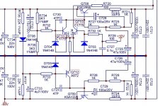
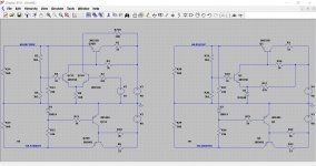
I attached the sheme of the 68V rail I you want to throw a look.
Attachments
Last edited:
Thanks 🙂 I'll have a look at it later.
It would be useful to know the voltage across each 33 ohm fusible as that gives a clue to the normal current draw of the circuitry the reg supplies. Also the incoming voltage to those 33 ohms.
It would be useful to know the voltage across each 33 ohm fusible as that gives a clue to the normal current draw of the circuitry the reg supplies. Also the incoming voltage to those 33 ohms.
So...
Q710. The purpose of this transistor is a bit of a mystery. It seems tied in to the 18 volt rail, perhaps to ensure a reliable start sequence. R723 seems very low in value and the circuit should as far as I can tell work correctly even with values as high as several k ohm.
A 2k2 reduces the dissipation in Q710 from around 900mw to under 500mw with no change in the regulated rails.
Q711 shouldn't be getting hot tbh. Maybe proximity of Q710 is heating it.
Q712 also shouldn't be hot as it dissipates under 200mw.
I've assumed around 115ma through the 33 ohms and an input of 80 volts.
And thinking about it a bit more... Q710 is simply an emitter follower taking the 18 volt rail as a 'reference' and applying that to the emitter of Q711.
The circuit looks like it could be modified to replace R731 with a Zener thus making it more conventional.
The dissipation I quoted earlier was wrong, Q710 dissipates around 500mw, not 900 as I stated. R720 should be tweakable up to around 6k8 which should bring the dissipation down to under 150mw.
The circuit looks like it could be modified to replace R731 with a Zener thus making it more conventional.
The dissipation I quoted earlier was wrong, Q710 dissipates around 500mw, not 900 as I stated. R720 should be tweakable up to around 6k8 which should bring the dissipation down to under 150mw.
Thanks for your effort, there are 70,1V across the fusible resistor and 89,2V incoming.
I look what resistors I have or need to buy.
Q710 and Q711 are directly behind each other. I got 105°C between both.
Q712 is a bit cooler, but not much.
I attached a picture of this area during disassembling.
C728 and C729 lost most of their capacity and have burn marks on the side where the transistors are.
Attachments
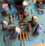
It has that look of 'running hot' 😀
So 90 volts on one end of the 33 ohm (incoming) but there won't be 70 volts 'across' it. Even 20v across it (90 volts on one end and 70 on the other) would be power dissipation of 12 watts into 33 ohms. That would frazzle things.
I would have thought something like 5 or 6 volts dropped across the 33 ohm tbh.
90 volts incoming rather than the 80 that I guessed at actually reduces the dissipation in Q710 by quite a big amount, strange but true. Increasing R720 still works in reducing the dissipation though and would pull it down from around 250 to 300 milliwatts to around 150 millwatts. That's for a 6k8 resistor.
Try it and check that the regulated rails are still correct. They should be.
That's strange.
I measured again, still 20V difference between both ends.
"After" the resistor to ground gave me 19,15V which makes no difference.
I could measure only one side because the pcb is still in the case.
I'll check the other tomorrow.
I measured again, still 20V difference between both ends.
"After" the resistor to ground gave me 19,15V which makes no difference.
I could measure only one side because the pcb is still in the case.
I'll check the other tomorrow.
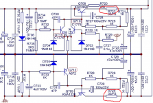
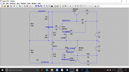
I'll have to leave it for tonight but just to be sure we are looking at the same thing... the 33 ohm here.
20 volts difference from end to end would mean a current of 600 milliamp was flowing. That just seems an awful lot for a small regulator type PSU. The 33 ohm would need to be at least 12 watt rated (W=I*V). They would be physically very large components.
Something doesn't add up there 🙂
20 volts difference from end to end would mean a current of 600 milliamp was flowing. That just seems an awful lot for a small regulator type PSU. The 33 ohm would need to be at least 12 watt rated (W=I*V). They would be physically very large components.
Something doesn't add up there 🙂
Attachments
There seems to be someting wrong. At least with R723.
First I wanted to replace every fusible resistor and unsoldered them.
Because I couldn't find replacements I checked resistance and put them back.
As i measured the resistance of R723 yesterday as it was hot, I got first infite and after a few seconds the resistance starts to fall.
I'll take a closer look later this afternoon.
Both resistors are faulty.
I've orderd them but it will take a few days.
A zener and R720 as well, I'll report back.
Thanks so far for your help.
I've orderd them but it will take a few days.
A zener and R720 as well, I'll report back.
Thanks so far for your help.
And thinking about it a bit more... Q710 is simply an emitter follower taking the 18 volt rail as a 'reference' and applying that to the emitter of Q711.
The circuit looks like it could be modified to replace R731 with a Zener thus making it more conventional.
I used the time until the parts arrive to think about the mod with the zener.
If the zener is used as reference, it should make Q710 unnecessary.
Of cause I have to set the voltage divider (R734/R735) to fit the zener and the matching output voltage.
But will be there any advantage except that it is more conventional?
I looked in different shemes of NAD and they seem to avoid using a zener in similar regulators.
Maybe that has something to do with noise?
So the regulation of this rail is bound to the stability of the 18V rail.
But I can't answer which way will give at better PSU.
I can't say which would be better either. Noise is non issue though (imo) using a properly decoupled Zener.
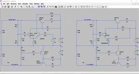
Quick simulation with an 18v zener and a 6.2 volt vs the original.
Quick simulation with an 18v zener and a 6.2 volt vs the original.
Attachments
Thanks for your simulation!
How do you calculate the zener resistor R17?
It seems to draw relatively much current through the zener.
I've ordered a vishay BZX55B18 18V zener which should do the job.
Another question, I like to add an resistor around 3k between collector of Q712 and base of Q709 to reduce the dissipation of Q712.
Is there anything that speaks against it?
I didn't calculate it if I'm honest. That resistor is often added to ensure correct start up behaviour although in practice its something I've never found necessary. Just a milliamp or so needed if you use it.
Zener current is 7.5ma with it and around 6ma without.
Given that Zener voltage aren't absolute and have a tolerance you may need to tweak one of the voltage setting resistors very slightly to get the exact output voltage you want.
Adding a resistor to limit dissipation is OK although how high you can go will depend on the gain of the pass transistor.
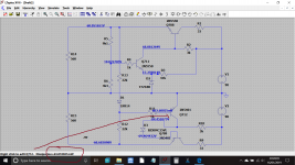
These are the simulated voltages.
Another option could be to add a Zener as shown. 15v could be a bit extreme but you can see how it reduce the dissipation.
Zener current is 7.5ma with it and around 6ma without.
Given that Zener voltage aren't absolute and have a tolerance you may need to tweak one of the voltage setting resistors very slightly to get the exact output voltage you want.
Adding a resistor to limit dissipation is OK although how high you can go will depend on the gain of the pass transistor.
These are the simulated voltages.
Another option could be to add a Zener as shown. 15v could be a bit extreme but you can see how it reduce the dissipation.
Attachments
I mixed up test and max zener current, thats why i thought 1.5mA is pretty much...
Test current is 5mA, it should be fine without that resistor, but it can be used to shift the working area too.
There are some jumper wires in the circuit which can be used for additional parts.
That should look pretty neat.
Test current is 5mA, it should be fine without that resistor, but it can be used to shift the working area too.
There are some jumper wires in the circuit which can be used for additional parts.
That should look pretty neat.
My local dealer is not able to get all fusible resistors.
They was ordered but canceled by wholesaler.
Can I use a resistor and a smal fuse in series?
Thanks to the guidance of Mooly I simulated the circuit with LTSpice and I know the current (~123mA) through the resistor at expected load.
I found a datasheet for a comparable fusible resistor. Depending on time it is specified to fuse from 15 to 60 times of the nominal power.
Does that mean it does not fuse under 15 times of the nominal power?
That would give me a fuse around 7.5A?!
Last edited:
Right then..….. 🙂
One reason manufacturers use safety resistors is simply because they fail in a way that doesn't upset the customer. They don't smoke and they don't smell when overloaded, two things that frighten the customers.
On the basis that this is technically low voltage stuff and is 'isolated' via a mains transformer I'm going to say that as long as you understand the implications then its OK to use normal resistors here on the understanding that if an overload occurs then the resistor will smoke and burn before going open circuit. Obviously be sure that the resistor isn't next to anything flammable.
33 ohms @ say 150ma current is going to need a 1 watt part.
I would get the amp working first and then revisit the idea of whether to seek out correct fusibles/live with ordinary parts/fit in-line fuses with the resistor.
- Home
- Amplifiers
- Solid State
- NAD C272 refresh