what is the benefit of connecting the zener D004 and smoothing capacitors C014/C018 to regulated output voltages instead of connecting them to ground?
Connecting the Zener to the regulated output of any series regulator ensures it runs at a constant current at all times. If fed from the unregulated side it is subject to current variations and also ripple. The caps I would guess give the best noise and ripple rejection connected as they are. They also can be used to introduce a slight delay (slower rise time) of the rails and I see they are different values. That can be useful to minimise any unwanted behaviour on power up and power down and in logic circuits prevent race hazard situations.
Begin at the the right hand side of R009 and work through to the left. The -18v regulator is fed from the output of the -24 volt regulator. R009 has to be favourite. If its open the big question is 'did it jump or was it pushed'. In other words a one off failure or has there been a short on either reg that has taken the resistor out.I don’t understand how this circuit works or what I’m looking for
I imagine the black dot on it means 'fusible' or 'safety' resistor and these are special types that fail with no smoke or fire hazard when they go open. For testing only you can fit a standard type to get it all working.

Is there any thread on this site dedicated to this topic?Connecting the Zener to the regulated output of any series regulator ensures it runs at a constant current at all times. If fed from the unregulated side it is subject to current variations and also ripple.
Ok, so then I should start one.Not that I know...
It would be not good to dump a side discussion in this thread.
Ylli‘s post prompts me to wonder if I’ve misconstrued your drawing in post 18. I interpreted your accompanying text and enciircled blue region to indicate untested circuits. Plus comment in post 14.
But if the green highlights indicate lines that comply with labeled voltages, ie +/- 24V is working, that changes the picture dramatically. Would you clarify, please?
Thanks.
But if the green highlights indicate lines that comply with labeled voltages, ie +/- 24V is working, that changes the picture dramatically. Would you clarify, please?
Thanks.
Last edited:
Sorry for the confusion.Ylli‘s post prompts me to wonder if I’ve misconstrued your drawing in post 18. I interpreted your accompanying text and enciircled blue region to indicate untested circuits. Plus comment in post 14.
But if the green highlights indicate lines that comply with labeled voltages, ie +/- 24V is working, that changes the picture dramatically. Would you clarify, please?
Thanks.
I have verified +/- 18V and +/- 24V are not working.
I measured +1/-0.7V and around +/- 2V, respectively.
Yes, the the blue region is the region I’m testing for a fault.
Green highlights were an effort to make it easy to see those lines 🙂, I see that caused confusion instead. More detail is not necessarily better lol.
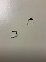
Good news I found R003 and R009 are open 🙂.
I might have 2 spare 10ohm resistors for testing.
It works after replacing R9 and R10. I am listening AM radio in both channels through my headphones right now! Apparently, R3 and R9 were the fault. Thanks very much for the help. I’ll check PS voltages again and replace the spare 10 ohm resistors with 1/4 Watt fusible ones per service manual. Any other things I should check to replace before wrapping this working Nad 7400 up? DC Offset is 10 and 15mV 🙂.
Both resistors had no signs of damage, as Mooly described. I checked the other suspects R10,R11 and Q003 (verified before) prior to powering up.
Both resistors had no signs of damage, as Mooly described. I checked the other suspects R10,R11 and Q003 (verified before) prior to powering up.
Attachments
Last edited:
Pleased to hear its OK 🙂
(You should just check those regulated rails are now at correct voltage)
Its a NAD... be happy its working 😀Any other things I should check to replace before wrapping this working Nad 7400 up?
(You should just check those regulated rails are now at correct voltage)
- Home
- Amplifiers
- Solid State
- NAD 7400 Receiver goes into Protection Mode: Help with troubleshooting