I hate to break this to you but we've been over Vbe measurements before. Perhaps I'm not being clear enough but that voltage measurement can be made directly across the transistors' base and emitter leads and since that is effectively a diode junction, in idling (quiescent) state, you should read around 0.7V, polarity depending on whether NPN/PNP and probe orientation. I thought I could subtract the measurements you made with respect to ground but as you say, there is some instability with the ground reference point. It should be the main (+/- 43V) supply ground, as The +/-71V supply is switched out until required.
Straight away though, I can see that Q401 and Q405 bases are joined yet you measure 0.41V at one base and -2.7V on the other. Something "basic" is wrong there - moreso than fluctuations the DBT will cause. Measure the voltage directly, base to base, to check the previous readings 😉
Straight away though, I can see that Q401 and Q405 bases are joined yet you measure 0.41V at one base and -2.7V on the other. Something "basic" is wrong there - moreso than fluctuations the DBT will cause. Measure the voltage directly, base to base, to check the previous readings 😉
Last edited:
Are all these voltage measurements with reference to zero volts on the power ground?
All power BJT have the collector in the middle and the base and emitter are the outside leads. This makes it easier to not short when taking the measurement. One touches the outside SIDE of the leadout where one cannot slip and accidentally short to the middle pin. A short to middle pin is likely to destroy the device and probably destroy other connected devices.
I think the last sentence should say base to emitter...............Vbe measurements ...............voltage measurement can be made directly across the transistors' base and emitter leads.................should read around 0.7V, polarity depending on whether NPN/PNP and probe orientation. ...................Measure the voltage directly, base to base, to check the previous readings 😉
All power BJT have the collector in the middle and the base and emitter are the outside leads. This makes it easier to not short when taking the measurement. One touches the outside SIDE of the leadout where one cannot slip and accidentally short to the middle pin. A short to middle pin is likely to destroy the device and probably destroy other connected devices.
Last edited:
I thought I was rather clear there. Check the last paragraph of my post again. I've drawn attention to the fact that TO92 input transistors Q401 and Q405 should have their bases connected. I attached a schematic covering the relevant input stage for reference, back at #97......I think the last sentence should say base to emitter....
I can see that Q401 and Q405 bases are joined yet you measure 0.41V at one base and -2.7V on the other.
I did make a 0.41V error in repeating Q401 base voltage but if the base of either transistor measures a different voltage (there is still 2.7V to account for) with respect to the same reference point, something is amiss - probably nothing to do with Vbe in that case. An obvious way to verify the difference is to measure from base to base, directly on the transistors.
Last edited:
I do remember being previously advised on E/B measuring procedure. But for some reason, I thought at one point early on, I had measured across E to B but was instructed to measure voltages present at each pin instead. There's nothing wrong with my memory, it's just short.
So measuring across Q401 E to B shows not .7v but .5. Q405 though shows 1.6v.
I noticed that at a "cold start" base voltages were zero, or close to it, but the longer power is applied, the reading rise. For example, after immediate turn on, both base voltages were pretty much zero but then rose to (-) 1.6mv. Not zero but at least they are the same.
Regarding the ground point, I am and have been using the C505/C506 common - where the pins join. The schematic says there should be +/-43v but when I measured across each capacitor's pins, all I got was +/-26v. Checking C509/C510 where there is supposed to be +/-71v, it is here I get +/-43v.
I measured E to B voltages across all the odd number transistors and none were .7v Seven were around .5v but the others were less except Q405 which was 1.6v.
EDIT: Base to base on those two transistors is zero volts.
Last edited:
Too late for a second edit.
I checked +/- of BD502 and got +/- 43v. According to the schematic, there is supposed to be +/-71v. Can this mean BD502 is faulty?
I checked +/- of BD502 and got +/- 43v. According to the schematic, there is supposed to be +/-71v. Can this mean BD502 is faulty?
OK, so you find no voltage difference between the Q401,405 bases but somehow, one base measures 2.7V and the other 0V wrt C505/506 common or ground. That is a logical problem. I can only guess the supply voltages changed between measurements as you suggest and points to further problems.
The DBT is doing its job in limiting current and must also limit voltage to do that. You seem to have about 60% DC supply voltages in all cases. Coincidentally, 43V is close to 60% of 71V. That is sure confusing but I think it is the situation Change the lightbulb (!) and I think the voltages will change to something distinctly different.
First, check the high voltage AC supply to BD502 rectifier bridge. +/-71V supplies would require AC volts of (71 +0.7V)/√2 each rail. 60% of that figure should be around 50VAC wrt ground or simply measure the total AC across fuses F501,502 where you'd hope to find ~100VAC. I hope there is no problem there.
Regarding the transistors, I would directly compare Q405 Vbe with Q407 and pull 405 if you find normal Vbe there. Measuring only 0.5V for Vbe seems to be usual with your meter - no criticism there as Extech products are well respected but is it possible there is a battery problem? Now diode check Q405, comparing with any new TO92 or whatever small transistor you have lying around and of course, check for a C-E short. Just saw your post - more likely the AC supply.
The DBT is doing its job in limiting current and must also limit voltage to do that. You seem to have about 60% DC supply voltages in all cases. Coincidentally, 43V is close to 60% of 71V. That is sure confusing but I think it is the situation
Change the lightbulb (!) and I think the voltages will change to something distinctly different.First, check the high voltage AC supply to BD502 rectifier bridge. +/-71V supplies would require AC volts of (71 +0.7V)/√2 each rail. 60% of that figure should be around 50VAC wrt ground or simply measure the total AC across fuses F501,502 where you'd hope to find ~100VAC. I hope there is no problem there.
Regarding the transistors, I would directly compare Q405 Vbe with Q407 and pull 405 if you find normal Vbe there. Measuring only 0.5V for Vbe seems to be usual with your meter - no criticism there as Extech products are well respected but is it possible there is a battery problem? Now diode check Q405, comparing with any new TO92 or whatever small transistor you have lying around and of course, check for a C-E short. Just saw your post - more likely the AC supply.
Last edited:
I seem to have another error above. The estimated AC voltages apply to normal mains power. At 60% with the DBT, either rail supply will measure less at 30VAC wrt ground or 60VAC across F501,502. It's only 6pm here but I should also get more sleep 
If the primary circuit Bulb has reduced the secondary voltage to ~ 60% of normal, that means there is a high current draw on the secondary. Don't remove the bulb yet.
OK, so you find no voltage difference between the Q401,405 bases but somehow, one base measures 2.7V and the other 0V wrt C505/506 common or ground. That is a logical problem. I can only guess the supply voltages changed between measurements as you suggest and points to further problems.
The DBT is doing its job in limiting current and must also limit voltage to do that. You seem to have about 60% DC supply voltages in all cases. Coincidentally, 43V is close to 60% of 71V. That is sure confusing but I think it is the situation
First, check the high voltage AC supply to BD502 rectifier bridge. +/-71V supplies would require AC volts of (71 +0.7V)/√2 each rail. 60% of that figure should be around 50VAC wrt ground or simply measure the total AC across fuses F501,502 where you'd hope to find ~100VAC. I hope there is no problem there.
Regarding the transistors, I would directly compare Q405 Vbe with Q407 and pull 405 if you find normal Vbe there. Measuring only 0.5V for Vbe seems to be usual with your meter - no criticism there as Extech products are well respected but is it possible there is a battery problem? Now diode check Q405, comparing with any new TO92 or whatever small transistor you have lying around and of course, check for a C-E short. Just saw your post - more likely the AC supply.
I read this post via my cell while on shift earlier today, prior to the two that followed being put up. I'm thankful I saw them after arriving home because the first thing I planned on doing was increasing bulb wattage of the DBT.
Before I do anything further, I must confirm my ignorance and ask what is wrt ground? The first thing that came to mind was "with red to" ground.
wrt is with respect to
But most would hook the black lead onto the reference node and use the red probe to take readings around the board.
For Vbe measurments the ref is the emitter. Hook the black lead onto the emitter and probe the base with the red.
NPN should give +600mV ±100mV, PNP should give -600mV ±100mV
But most would hook the black lead onto the reference node and use the red probe to take readings around the board.
For Vbe measurments the ref is the emitter. Hook the black lead onto the emitter and probe the base with the red.
NPN should give +600mV ±100mV, PNP should give -600mV ±100mV
I have not abandoned this project but there has been no time to spend with it. My employer does not consider 15 to 17 hours per day in the cab anything unusual and has also taken to requesting forfeiture of one or both days off per week to cover manpower shortages. The fact that no one stays with them long because of long hours, low pay and no benefits does not seem to phase them.
Excuse my my venting.
I am still in observance of Andrew T's advice of not upping the DBT to a higher wattage so the 40 watt is still in place and the following measurements are under that condition.
*AC supply to BD502 is 38.5 volts.
*Voltage at F501 and F502 wrt ground is the same - 38.5 volts
*Wrt ground, compared VBE of Q405 (B=0 volts - E=1.5 volts) with Q407 (B=minus 29mv - E=.55 volts). FWIW, the zero volts at Q405 B was unstable. Readings fluctuated +/- single digit millivolts.
*Pulled Q405 for diode check and it looked OK. Reference checked a random small transistor, got no anomalous reading so assume meter is fine. New batteries less than a month ago.
*Checked for VE short, none found so re-installed Q405.
If considered safe to do so, I will sub a higher wattage bulb and repeat the above.
EDIT: Would allowing the unit to remain powered up for any length of time prior to voltage checking be recommended?
Last edited:
I do agree that the low wattage bulb you are using in your DBT may be causing you complications in your readings. Altho the idle current draw of your amp appears to be around 200W, I would use at least a 60W bulb for any kind of power amp.
Again, too late for a second edit.
Neglected to include in my previous post that across vBE for Q405 is 2.38 volts and Q407 .58 volts.
Will try upping to 60W bulb and see what happens.
Neglected to include in my previous post that across vBE for Q405 is 2.38 volts and Q407 .58 volts.
Will try upping to 60W bulb and see what happens.
I won't comment on your employer's attitude to legal working hour caps and the high safety risks being run. It speaks for itself, under any sane government and legislation. Leaving may just be a matter of time and your remaining health.
The amplifier though, can only be dissipating up to 20W if 40% of the supply voltage is dropped in passing through a 40W globe. As the DBT is in series with the load, the total power dissipated by the amplifier plus the bulb cannot exceed the bulb's 40W rating alone. Both devices then, can only share up to 40W, quite a convenient safety limit and why a bulb may be preferred.
If a 60W bulb were used, we would expect the current and supply voltages to rise a little, but still be limited somewhat by the amplifiers' own bias current regulation circuits, assuming they are now functional. The bulb should still be dim though. but the rail voltages will be accordingly higher and may simply lead to a repeat performance. I suggest as AndrewT does, sort out what can be sorted at low voltage first.
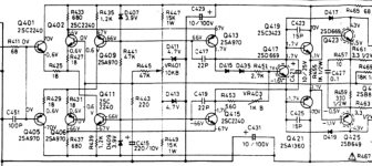
You can see from the schematic that the test voltages around Q401, 2, 5 & 6 are all around the same. Vbe is always 0.6- 0.7V and because each time you post measurements, they are different, you should quote Vbe just like it says - just the Voltage directly between base and emitter. D407 and 409 zeners keep the base voltage ~3.9V below the rail voltage, whatever that is - possibly still 43V but it isn't critical. Of course the voltage across zeners should be 3.9V and all Vbes should be still be 0.6-7V. If not, check voltage across the associated resistors. After comparing with what you measure in the other channel and deciding that it is probably fine and you don't have a resistor, diode or supply voltage problem, then pull and replace Q405.
The amplifier though, can only be dissipating up to 20W if 40% of the supply voltage is dropped in passing through a 40W globe. As the DBT is in series with the load, the total power dissipated by the amplifier plus the bulb cannot exceed the bulb's 40W rating alone. Both devices then, can only share up to 40W, quite a convenient safety limit and why a bulb may be preferred.
If a 60W bulb were used, we would expect the current and supply voltages to rise a little, but still be limited somewhat by the amplifiers' own bias current regulation circuits, assuming they are now functional. The bulb should still be dim though. but the rail voltages will be accordingly higher and may simply lead to a repeat performance. I suggest as AndrewT does, sort out what can be sorted at low voltage first.
You can see from the schematic that the test voltages around Q401, 2, 5 & 6 are all around the same. Vbe is always 0.6- 0.7V and because each time you post measurements, they are different, you should quote Vbe just like it says - just the Voltage directly between base and emitter. D407 and 409 zeners keep the base voltage ~3.9V below the rail voltage, whatever that is - possibly still 43V but it isn't critical. Of course the voltage across zeners should be 3.9V and all Vbes should be still be 0.6-7V. If not, check voltage across the associated resistors. After comparing with what you measure in the other channel and deciding that it is probably fine and you don't have a resistor, diode or supply voltage problem, then pull and replace Q405.
I believe I wrapped my head around the fact that increasing the DBT's wattage increases the voltages present on the board.
I noted the expected schematic voltages and with a 60W bulb in place, took voltage measurements at D407 and D409. I realize now that the voltages will be lower than specified but should be consistent.
Those at D407 seem to be in line but not so with D409. The anode side was ~97mv whereas the cathode was 49 volts.
I did as suggested and checked the associated resistors and found R447 and R449 deficient. Both are 15K 1W and both had low voltages at one end of about +/- 4.5 volts whereas the other end was +/- 53 volts. Both of these resistors are brand new replacements for burnt originals.
Is it logical to conclude that D409 is responsible?
Take a close look at where R447, 449 are connected. There is no • (meaning connection) between those resistors and the 3.9V zener diodes at the other (lower voltage) end of either. The lines just cross over and actually connect to either end of VR401 and 4.7V zeners D411, 413.
The voltage across VR401 should be quite low at 4.5V (i.e. when full supply voltage is applied) and the voltage drops across the fixed resistors should be correspondingly high, evidenced by the 1W rating. The pot. is only there to adjust any small residual DC offset at the output.
I think you just need to check the diode voltage across D407, 409 and compare with that across D408, 410. The associated resistors are R441, 442 and the collector resistors of all 4 transistors, both channels. That's R435, 439 and R436, 440. However, if you notice a problem in comparing the 4.7V zeners too, by all means compare that section. The fact that the original 1W resistors were burnt out does suggest something dire there in the way of fault current and that could only mean fried transistors which probably affects all sections.
BTW, the function of transistors Q409, 411, 410, 412 is to regulate only a couple of mA bias current through the 2 mirrored pairs of input transistors pairs in each channel. The diodes are a stable voltage reference that in turn, makes current stability possible.
400-600mW rated, through-hole or DO35 style zener diodes of the specified voltage would do fine if replacements are needed. Fairchild still make types BZX79c3v9 and BZX79c4v7 which covers either zener type you may need to replace there. There are plenty of manufacturers but some competitor numbering systems are difficult to follow. This one will be widely recognized.
Sorry if I seem to repeat myself but others reading the thread may not be attuned to the problems without something in front of them. It can sure be difficult to imagine each component, assembly, circuit operation and fault possibility as it appears. It can be fun if it's a simple matter but this isn't simple and needs regular reassessments to keep on track.
Well, Christmas will soon be a welcome break, a cool one for me, I hope 😎, perhaps a bit warmer for you guys up there
Attachments
A cool one? Isn't it 30/40 C in your corner of the globe? Around here, it was below zero and snowed for a few days. Now back to + single digits C and rain.
I intend on making those measurements as per your instructions this weekend. There are no celebratory engagements for me to participate in.
Earlier today I was nearby the electronics shops and in anticipation of needing them, stopped in for some of those small Zener diodes. I was unable to get 400 to 600mw but 1 watt were available in 3.9v and 4.3v. They were inexpensive so in case they were suitable, I took some of each.
If new diodes are called for, can I use 1w in lieu of 400/600mw? And if so, is it OK to substitute 4.3v for 4.7v?
What I got have the same package style and physical size does not look to be an issue as far as hole spacing is concerned.
If a no go, I will bite the bullet and order those Fairchild's online.
Daily air temperature varies in around 2 week cycles here in summer. 40C is rare on the coast but it happens and is totally debilitating unless you have a several kW rated air conditioner and can stay indoors 24/7. Some holiday seasons, we get a relatively cool 25-30C for the duration and this is just fine for what we like to do outdoors. What we wish for and what we get aren't always the same, but hopes are what I'm sayin' there.
As checking the voltage across a few diodes only takes a few minutes, I'd have done that before buying anything. I don't see too much of a problem in fitting a 4.3V rated zeners in lieu of 4.7V there. It would work with only a small reduction in the range of VR401 adjustment, better if you change both diodes. However, it would remain as something else to adjust and make good later. Using 1W rated diodes probably won't hurt though. If either diode has failed, I'd look at C429 (10uF/100V) and R445 too. If D407or 409 has failed, check R441.
As checking the voltage across a few diodes only takes a few minutes, I'd have done that before buying anything. I don't see too much of a problem in fitting a 4.3V rated zeners in lieu of 4.7V there. It would work with only a small reduction in the range of VR401 adjustment, better if you change both diodes. However, it would remain as something else to adjust and make good later. Using 1W rated diodes probably won't hurt though. If either diode has failed, I'd look at C429 (10uF/100V) and R445 too. If D407or 409 has failed, check R441.
I ate late this afternoon, no need for dinner so I measured voltage drops across those diodes still with a 60W DBT:
D407-138mv, D409-47mv, D408-3.5v, D410-3.5V.
Since 407/409 were low I assumed they were faulty so lifted a leg of each for an out of circuit diode check and they appear to be good - OL in one direction and .685 the other.
Voltage drops across resistors R441/442 were 100.7 volts & 97.7 volts respectively.
Concerning R441 / 442 / 435 / 439 / 436 / 440 - I compared schematic voltages (if I deduced them correctly that is) and again this is with a 60W bulb in place and wrtg. There seems to be some consistency.
R441 should be +/-66 volts - actual was -48.4 volts & +49.5 volts
R442 should be +/-66 volts - actual was -48.7 volts & +48.7 volts
R435 should be +71 volts & +67 volts - actual was +53.4 volts & -53.5 volts
R439 should be -70 volts & -67 volts - actual was -53.4 volts & -53.5 volts
R436 should be +70 volts & +67 volts - actual was +49.6 volts & +52.5 volts
R440 should be -70 volts & -67 volts - actual was -49.2 volts & -49 volts
Those voltage drops across D407/409 seem to be the most glaring fault so I was expecting that the out of circuit check would show them to be bad but it didn't so that puzzles me.
I hope you have a wonderful time over the holidays Ian and look forward to your input whenever that may be.
Checking zener voltages isn't quite the same as normal PN diode or transistor junctions. A DMM is not enough for testing more than about 2V in diode drop voltage. You need to apply a sufficient stable reverse voltage of say 5V above the nominal zener voltage, via a suitable resistor, say 1k, to restrict current from burning the diode out. Then you can measure the zener voltage at (in this example) 5-10 mA current. Though not essential for testing, a 1W, 4.7V zener (1N4732A or BZX85c4v7) is specified at a much higher test current of ~ 50 mA, as on the datasheet but I don't recommend that unless there is provision in the test jig for cooling the diode leads to keep a stable temperature: https://www.fairchildsemi.com/datasheets/BZ/BZX85C4V7.pdf
Otherwise, it helps to have a variable, regulated bench power supply for such small semiconductor testing. I bought a tiny cheap kit for one not long ago, based as usual on a 3 terminal adjustable regulator chip and it came complete with tiny mains rated transformer, power cord, small clear acrylic case and LED voltage display, all for AU $8. It only delivers up to 150mA at about 12V but that's fine for many test applications, You have to spend a lot more to get the flexibility and precision of a proper lab. power supply and that needs to be justified.
Your test voltages look mostly fine but there is no voltage drop across R435,439 and hence no bias current flowing through Q409 or Q411 and so, no bias current through the input transistor pairs Q401/402 and Q405/406 either. That needs scrutiny - there should be some 1-2 mA flowing through those, emitter to collector and double that for Q409, 411.
There's no need to report all measurements but you should be checking the Vbes of those transistors to see what the problem is there. If the zeners really are OK, there is certainly a problem with the transistors there but if you can't test the zeners, then replace them and recheck for a voltage drop across R435/439.
You know, I'm convinced this is not going to be easy without the gear and information needed to test components properly. There is a limit to what you can be certain of with just a DMM and often you need to build test jigs on a bit of circuit breadboard or even buy specialised instruments for cases where you can't calibrate test circuits for the necessary degree of accuracy.
Luckythedog (#70,72) was not kidding either about the problems of getting this amp sorted, particularly if you haven't the experience of repairing a number of conventional design amplifiers to build on. Hang in and do a bit of reading on the general amplifier design principles with some useful explanations at the ESP site, to help build up some more of the background knowledge: Elliott Sound Products - Audio Power Amplifier Design Guidelines If nothing else, the education will always prove useful somewhere in the future.
Thanks for the good wishes and have a nice Christmas yourself, when you can squeeze in a few hours relaxation for your own sanity and safety. I'm not going anywhere so i'll be watching anyway if you decide to keep on with the investigation and repairs. If I seem unclear, or off-track, just say so because I seem to get a number of queries running at once, this time year. Don't be surprised if I confuse some
- Status
- Not open for further replies.
- Home
- Amplifiers
- Solid State
- NAD 7240pe - all output transistors failed?