During the process of pulling and testing left side transistors, I found and corrected a faux pas so now the DBT now has the barest glow after initial turn on.
I also found two 25 volt 10mV capacitors at C421 & C422 that shot their bottoms out so I replaced with same.
And Q419 is bad, a 2SC3423. I would replace it along with Q420.
I saw in thread....
http://www.diyaudio.com/forums/solid-state/112227-about-vas-drivers-transistors.html
....the implication that a KSC3503 can be substituted. Its CB & CE voltage is 300 volts - twice that of a 2SC3423. I have two KSC3503's and both are suffix D which the data sheet says has an HFE of 60 to 120 whereas the 2SC3423 data sheet says minimum HFE is 80.
Does that eliminate substituting KSC3503 for 2SC3423 in this application or would it be acceptible?
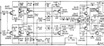
Good that you found the problem with the DBT. AndrewT was right to call attention to the brightness being a particular problem. I'm reposting the circuit snip showing the location of these 2SC3423/A1360 pre-drivers for others who may be following.
You've picked probably the best candidate(s) available from the types commonly available now and though the originals are extremely fast with an Ft of 200 Mhz and COB of only 1.5 pF, these aren't too far behind for the application, at 60 MHz and 2.5pF. I would still be wary of instability (oscillation) which would probably show up as mystery heating of the output stage when there is no signal and only normal bias current. Also, a brighter glow from the DBT (increased load) is indicative of something like this being amiss.
https://www.fairchildsemi.com/datasheets/KS/KSC3503.pdf
HTTP 301 This page has been moved
I suggest you replace the complementary pair with 2SC3503/A1381, rather than just the one transistor though. I would not be too concerned about Hfe as it will most likely be higher than minimum on test and you can use a cheap tester or DMM with transistor tester for this on these low current parts, if need be. If their counterparts in the other channel are OK, leave well enough alone as a reference, since the more changes made at once, the more likely the plot (and functionality) will be lost. Retain all functional parts too, just in case. Keep at it 🙂.
Last edited:
Replacing the transistor pair makes sense although I must get the KSB1381. I looked at two suppliers websites and both have them on hand. Since shipping will be about $8 I thought I'd order 20 or so along with more KSC3503.
The reason I have two of the latter is they were leftovers from something I was tinkering with last spring. I special ordered them locally at a cost of $2 each and was told at the time they were discontinued. If, as you say, among currently available transistor this is the best of its type, it seems prudent to have some handy should I run into a future need.
I anticipate the soonest I shall have them will be in 6 days, this upcoming Saturday.
You recommend leaving the originals in the right channel alone for a reference. Does that mean in perpetuity or just at the onset for comparison?
Considering I'll have the parts, my inclination would be to have both channels symmetrical when finished. If, that is, it actually does get finished.
Earlier this week, I received the KSC3503/A1381 transistors and that was to be the cue to start transistor replacement. Although it's not needed for those, I had on hand thermal compound for those that do but it seems it's the wrong stuff. A pity I did not recall doing so, because in 2014 I posted on AK asking if what I had was suitable but it was not. It is grey not white, intended for computer usage and conductive.
I will install those latest arrivals as they are free standing, not on a heat sink.
So I am delayed again until I can get the proper compound which I will pick up tomorrow. I do not think I'd have much success hitting any of the auto parts stores that are open today (Sunday) on the off chance they'd carry it.
The past couple of weekdays I really needed to use the hour or so I had on evenings after work as "down time" (read sleep) thinking I could get this NAD receiver back together today. I should have anticipated that something would prevent this as the fruit of my Karma tree always seems to hang just out of reach.
62V,
if the drivers are encased in plastic, then you can use a conductive type of Thermal compound.
It's the exposed metal tab that could short to the heatsink if you used conductive.
if the drivers are encased in plastic, then you can use a conductive type of Thermal compound.
It's the exposed metal tab that could short to the heatsink if you used conductive.
62V,
if the drivers are encased in plastic, then you can use a conductive type of Thermal compound.
It's the exposed metal tab that could short to the heatsink if you used conductive.
Thanks Andrew but I am going to need the proper stuff. Some transistors with the metal tab have their own individual heatsinks and although there is no mica insulator, thermal compound was used on the originals. Plus, there are the main outputs with mica insulators which also have compound that needs re-applying.
All the original parts in the output stage are standard case types with exposed metal contact plates so there's no case for using goop that contains silver powder. It occurred to me that if you try to replace the 2SD669/B649 drivers though, you won't be able to get the Hitachi originals and will only find Chinese copies. These are sometimes now TO126ML "full pack" or insulated types which may not be ideal replacements for a number of reasons. Watch the details of what you buy - sellers assume you can accept whatever they have that has a similar part number.
HSD669A pdf, HSD669A description, HSD669A datasheets, HSD669A view ::: ALLDATASHEET :::
HSD669A pdf, HSD669A description, HSD669A datasheets, HSD669A view ::: ALLDATASHEET :::
All the original parts in the output stage are standard case types with exposed metal contact plates so there's no case for using goop that contains silver powder. It occurred to me that if you try to replace the 2SD669/B649 drivers though, you won't be able to get the Hitachi originals and will only find Chinese copies. These are sometimes now TO126ML "full pack" or insulated types which may not be ideal replacements for a number of reasons. Watch the details of what you buy - sellers assume you can accept whatever they have that has a similar part number.
HSD669A pdf, HSD669A description, HSD669A datasheets, HSD669A view ::: ALLDATASHEET :::
Was hoping to get home 2 hours ago but on the way, I encountered and towed a stranded car off of a very busy bridge. Talk about profanity from other drivers needing to squeeze by! Makes me wish I had the power to impose a similar situation on them and see how they like it.
Consequently, no time for any soldering tonight but I made sure to take a look at those X-China 2SD669/B649 transistors I got. They do have metal plates on the back and FWIW, the Hitachi logo on the front.
EDIT: And I did get some white "thermal grease" this afternoon.
Last edited:
I guess you are in the depths of winter now with ice, snow and short tempers everywhere. I wouldn't be on the road if I could help it in your location (typed smugly whilst sitting bare chested and sweltering in 30 plus °C temperature here!)
Probably OK with the Chinese copies - but don't look too closely at the look-alike Hitachi logo. It doesn't inspire confidence when that would still be a copyright infringement in western countries .
Probably OK with the Chinese copies - but don't look too closely at the look-alike Hitachi logo. It doesn't inspire confidence when that would still be a copyright infringement in western countries .
Am I being stereotyped🙂? The depth of winter in these parts is usually rain. Lots and lots of rain but it can and has snowed. If a few centimetres sticks, it usually paralyses everything. We're at the base of mountains so hills aplenty and some don't know how to drive on snow/ice. There are many new area residents with money and expensive cars who think the more they cost, the better they stick to the pavement. In recent winters It seems that most of the vehicles seen at the roadside (or more often off the road) are fast ones.
I think those guys are everywhere, rain or shine. 'pity that neither intelligence, money or safe vehicles and roads have anything to do with appropriate social behaviour.
I made an observation that would be ironic if I imagined it right.
Last night I was home after only a 15 hour day (lucky me) and so installed the new BD911/912 Darlington transistors. I have taken to observing the DBT (still with 40W) after soldering in each new transistor and it displayed a dim glow each time except after the last Darlington. The lamp was dark, no glow. First thought was a fuse but no. I checked the DBT itself and the outlet it was plugged into but both were fine. I must shift the receiver's position to work on it and doing that caused the DBT to glow. Turned out that manipulating the power cord where it enters the chassis interrupted the power. I suspect a break at the plastic wire stay clàmp/clip. So I need to fix the power cord and plan to cut off the offending portion shortening it a bit.
My "what if speculator" kicked in and made me wonder if an intermittent power cord prompted a previous owner to hack away at the output transistors, get frustrated and chuck the receiver away.
I will start on installing the main output transistors this weekend.
The intermittent AC power cord issue turned out to be one side was not soldered where it entered the chassis and looked like it had been that way since day one. It's soldered now.
All output transistors have been installed and the DBT was used after connecting each one individually. All looked good.
Went to check and adjust the bias. Right side was low so I brought it up to factory spec 28mv +/- 2mv. Left side read "0" but moving VR403 in either direction had no effect.
To measure bias I had the meter leads across R471 and while connected, switched the meter to ohms. Even though it's supposed to be a 1 ohm resistor, I got 1.5 ohms (in circuit) and likewise for it's counterpart R472. With values that low, I guess variance like that is acceptable?
Also checked end to end of VR403 and got .884K ohms and combined readings of wiper to each end added up to about the same. VR403 is supposed to be 1K so it appears that it's OK too?
Any suggestions?
Unusual problem with the cord - I could imagine the owner (or partner) yanked it out when they heaved the amplifier in a fit of anger but probably nothing as dramatic 
There may be charge on the power supply caps that's interfering with resistance measurements. You won't get much sense from in-circuit resistor measurements because they involve the meter applying voltage to the circuit as well as the resistor and those readings are on the wrong side of 1 ohm for what you'd expect if a related component was faulty. If both channels measure similarly, it's unlikely to be much of a problem. Consider that R471,2 are shorted out after test and setup in the factory so unless they suffered an identical 50% drift in value without any current at all, they are likely still within 5% of their nominal value.
If you can't get bias in the L channel, you may not have cleared all the original faults. With power on, as you've already done, check Vbe measurements on the semis Q401-429 (odds) in that channel. Also recheck for C-E shorts as it's nothing for small-signal TO92 transistors to blow silently in a fraction of a second again, if there are still faults like other semi shorts there. Bias adjustment is done by trimming a small DC current fed via trimpot from Q415 collector to Q417 base so if the requisite +/- 1.7 voltages aren't there at the collectors of the VAS transistors, Q413, 415, you wont have any current to adjust. Check the schematic's DC voltages around there.
Attachments
It has been a few days since I've had even a spare moment. The weather, and covering for injured co-workers has made my already long days even longer and until things change, I seem to be somewhat expected to do a 6 day week instead of 5.
I have yet to measure the EB voltages of the specified transistors, that won't be possible until the weekend. But I did check for CE shorts this morning. All but Q403/407/409/413 produced a reading of OL so those appear to be OK.
Those other four had resistances. Q403: 28M ohms, Q407: 35K ohms, Q409: 16K ohms, Q413: 39M ohms.
I checked to see what transistors were in place and all were right except for Q413. I cannot recall at the moment why I did but I installed a 2SA992 in place of a 2SA970.
I will post the BE voltage in a couple of days but would I be wise to replace the four shorted transistors beforehand?
The resistances you measure across C-E only have to be higher than other circuit resistances that are also in play. You wouldn't call readings of 16k - 39M shorts in case. To be more certain of what to expect, compare with the other channel readings but I don't think there's any problem there. BTW, we discussed earlier that 2SA992 is a drop-in replacement for 2SA970, assuming they are from similar Hfe (gain) groups. Perhaps you forgot that but it means they're interchangeable and no problem swapping...... All but Q403/407/409/413 produced a reading of OL so those appear to be OK........Those other four had resistances. Q403: 28M ohms, Q407: 35K ohms, Q409: 16K ohms, Q413: 39M ohms......I checked to see what transistors were in place and all were right except for Q413. I cannot recall at the moment why I did but I installed a 2SA992 in place of a 2SA970.....
I completed the E & B voltage measurements. It was an arduous task for me as I repeated it three times being hampered by poor lighting, poor eyesight and poor ergonomics. I was not satisfied the first round was accurate so repeated it. That produced such different results that I performed a third. I experimented with chassis ground and then re-soldering a ground lead to the large capacitor's negative - just in case there was ground issue.
If of any consequence, the DBT had a 40W bulb.
I apologize for presenting such a tedious list, expecting you to read and comment but here they are along with what is indicated on the schematic:
Schematic specs
Q401 E: (-).6v.......B: 0v
Q403 E: (-).6v.......B: 0v
Q405 E: +.6v........B: 0v
Q407 E: +.6v........B: 0v
Q409 E: +67v.......B: +66v
Q411 E: (-)67v......B: (-)66v
Q413 E: +67v.......B: +66v
Q415 E: (-)67v......B: (-)66v
Q417 E: (-)1.7v.....B: (-)1.1v
Q419 E: +1.1v......B: +1.7v
Q421 E: (-)1.1v....B: (-) 1.7v
Q423 E: +.5v........B: +1.1v
Q425 E: (-).5v.......B: (-)1.1v
Q427 E: 0v............B: (-).5v
Q429 E: 0v............B: (-).5v
Actual measurements
Q401 E: +.41v.....................B: 0v
Q403 E: (-).61v...................B: (-)30.2mv
Q405 E: (-)3v.....................B: (-)2.7v
Q407 E: +.54v.....................B: (-)29mv
Q409 E: +42.8v...................B: +39.4v
Q411 E: (-)42.7v.................B: (-)43.1v
Q413 E: +42.7v...................B: +39.3v
Q415 E: (-)42.6v..................B: (-)38.4v
Q417 E: (+).5mv to 1.5mv....B: erratic reading in mv
Q419 E: (-)1.2v....................B: (-)98mv
Q421 E: (-)1.3v....................B: (-)108mv
Q423 E: (-)3v.......................B: (-)1.3v
Q425 E: (-)2.7v....................B: (-)1.2v
Q427 E: (-)2.5v....................B: (-)2.9v
Q429 E: (-)2.6v....................B: (-)1.4v
Should I be checking the large diodes or the small ones for that matter?
Last edited:
- Status
- Not open for further replies.
- Home
- Amplifiers
- Solid State
- NAD 7240pe - all output transistors failed?