Yes, I read about dry solder joints too and that does not seem to be limited to this model. Since I noticed the situation with the output transistors right away, I did not look for faults like that at the onset. But I spent some time yesterday morning with an illuminated magnifier (better than nothing) looking for telltale rings. I heated and added a bit more solder to any that looked iffy.
Also yesterday morning, I ordered BD681 and BD682 along with the small fusible resistors and should be picking them up this upcoming Saturday morning. I will post again then, likely with the question "where do I start?"
Also yesterday morning, I ordered BD681 and BD682 along with the small fusible resistors and should be picking them up this upcoming Saturday morning. I will post again then, likely with the question "where do I start?"
You need to have all the replacements fitted now. Power up with the lowest rated bulb (40W?) you have and go around the voltages with your DMM again. i.e. those associated with your replacements as marked on the schematic, checking that you don't have awful discrepancies, heating or the smell of burning.
Mostly, voltages over a few volts will be proportionally lower than specified, as you might expect when the supply voltages are reduced but that's OK so long as the junction voltages (~ 0.7V) read correctly. If this step is apparently OK, the acid test is the DC voltage at the output, i.e. the connection of the Emitters of both Q427 & Q429 - 2SD1047 and 2SSB817. That should be very low, much less than 100mV.
If yes, change up the bulb to 60W and recheck for undue heating and the output DC voltage. Then you can also check signal output with a light load such as cheap headphones, maybe a simple computer speaker etc.
This all hangs on there being no residual error due to damage further back, such as at the small transistors of the input stage. I think you checked there already, but recheck the base voltage of Q417 and voltages through the following driver stage Q419, 421, 423,425 for "good measure". Perhaps I should have placed this in chronological step order but I figured you had checked these voltages earlier. A recheck won't hurt though, considering you are probably learning a bit more as you go along and maybe see the point to checking and rechecking DC potentials, particularly those that are signs that the whole amplifier or sections of it are working normally or not.
the low wattage bulb will drop a very low voltage if the current demand is also very low.You need to have all the replacements fitted now. Power up with the lowest rated bulb (40W?) you have and go around the voltages with your DMM again. i.e. those associated with your replacements as marked on the schematic, checking that you don't have awful discrepancies, heating or the smell of burning. ...........................
The cold resistance of a 115Vac 40W bulb will be around 30r to 33r.
The hot resistance will be around 330r.
When it burns bright, it is almost up to it's fully hot temperature and it's fully hot resistance. The bright bulb drops 90% to 95% of the mains voltage leaving the secondary output voltage around 1Vac to 5Vac. The DC at the supply rails is hardly able to turn on any BJTs.
Conversely when the bulb looks cold, no dim glow, the resistance is very low and the voltage drop is also very low. This results in 90% to 99% of the mains voltage appearing at the transformer. You end up with supply rails that are virtually at the normal operating voltage.
That is the first voltage measurement you take. A low voltage at the supply rails tells you there is significant current draw.
That tells you to look for where that excessive current draw is.
Ian, I've been stalled another week by the US Post. My order that includes those BD681 and BD682 Darlington transistors got misdirected. I anticipated picking them up this morning but they won't get to the Canada/US border now until this upcoming Wednesday. Which means I won't have them for another week - Saturday next.
You mentioned "needing to have all replacements fitted now". I presume that means no point in checking anything until everything is in place?
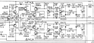
Thanks too for that schematic portion. In preparation, I already printed a zoom screen shot of the same section from HiFi Engine's manual but I think I'll do likewise with yours. Just in case there are more discrepancies.
Thanks AndrewT for the advise on the bulb. I already fitted the 40W bulb in the DBT and am ready to go.
You mentioned "needing to have all replacements fitted now". I presume that means no point in checking anything until everything is in place?
Thanks too for that schematic portion. In preparation, I already printed a zoom screen shot of the same section from HiFi Engine's manual but I think I'll do likewise with yours. Just in case there are more discrepancies.
Thanks AndrewT for the advise on the bulb. I already fitted the 40W bulb in the DBT and am ready to go.
To save blowing up new transistors I would fit a mains lamp in series with the amp.
I have also resorted to leaving output transistors out and feeding back driver output signal to LTP. This means you can power up amp without blowing output transistors if the bias is wrong.
If you have time on your hands you can go through every component and check it unpowered.
I have also resorted to leaving output transistors out and feeding back driver output signal to LTP. This means you can power up amp without blowing output transistors if the bias is wrong.
If you have time on your hands you can go through every component and check it unpowered.
I picked up the remainder of the needed transistors today and with those in hand, I thought it best to replace the burnt resistors first. Two of those are R455 and R456 which I assumed were 1/2 watt 68 ohm but they are not, they are 1/2 watt 1K ohm and I have none. I can get some but not before Monday. The shops that sell such things are all closed tomorrow - Sunday.
I shall do what I can with what little time I have in the evenings after work weekdays but chances are I will not have all transistor replacement done until a week from today - next Saturday.
I shall do what I can with what little time I have in the evenings after work weekdays but chances are I will not have all transistor replacement done until a week from today - next Saturday.
Tonight, I have only been able to replace 4 burned resistors one of which was the 1/2W - 1K ohm R455. Next I plugged the receiver into the DBT (with 40W bulb) in order to double check the voltages at the transistors specified a few posts ago. But within a few seconds of power on, R455 started smoking. I measured its voltage at approximately -40 volts and if I'm not mistaken the schematic says there should be 1.1 volts.
Examining the schematic prompted me to check voltage at transistor Q421 where I also obtained approximately -40 volts at B, C & E despite that it seems there should be -1.1 volts at E and -1.7 volts at B. I am a bit puzzled though because the voltage at C looks like it should be -70 volts.
I am also puzzled because the voltages at Q422 are the same as Q421 but R456 appears to be unaffected as in not burnt and discolored.
It seems now that the next step is removing Q421 and likely Q422 (2SA1360's) to test out of circuit.
Is it likely that the voltage discrepancy is caused by these transistors or might they be a casualty of something else?
Hi and welcome back. I need to brush up on this as I've already forgotten what I didn't even know about this amp. What's needed to help understand why voltages swing about wildly like that, is that when BJTs fail, they most commonly short out C-E as I've already said enough about.
That means it's as if you had a low value resistor between Collector and Emitter instead of a transistor. Yes, that will pull the floating 1.1V potential up towards the 43V rail, to which it's now shorted to and loading the power supply, causing the lamp to glow proportionally.
If you tested the transistors for C-E shorts as discussed, you would have had a good idea of how many parts had actually failed before you needed to power up. Any multimeter set to a low resistance range will do, it takes only a few seconds and the amp doesn't need to be powered to check for a short. So go over them, probes placed both ways for identifying a definite short - on all of those remaining, including any you replaced. The BD681, 682 being Darlingtons should also test the same but there are other junctions in there you can't access. All B-E emitter junctions should read around 0.7V either + or - polarity depending whether NPN or PNP type. It's a diode-like junction your measuring there, so it needs to be powered to check the forward voltage drop this way.
If I recall correctly, the R channel measured OK so you wouldn't expect the even numbered parts to smoke or show all the same signs - just the odd number parts, unless there are more problems to come there too.
I just found this thread and will give it a good read and try to help. About a year ago I repaired a NAD 3240 which is the amp only version, and it became a real quest, an intellectual challenge.
I should say, at the end of it all when it worked, it does sound great and is worthwhile to repair. It belongs to a good friend of mine who loves it, and I returned it to him working with the bag of transistors and resistors I'd been through.
I think the approach you're taking is good. Under fault conditions, especially faults in the B+ boost section, some transistors end up voltage stressed C-E, so always replace with original parts. Even then, there is a habit of cascading destruction of transistors in my case, and I went through at least three sets of output/driver/preamp transistors, even taking care.
Main points are that it is a very worthwhile, but difficult, repair IMO. So hang in there, and I'll read the thread and try to help, it may jog some memories !
LD
Something is wrong................Next I plugged the receiver into the DBT (with 40W bulb) in order to double check the voltages at the transistors specified a few posts ago. But within a few seconds of power on, R455 started smoking. I measured its voltage at approximately -40 volts and if I'm not mistaken the schematic says there should be 1.1 volts...............
Have you checked your Mains Bulb Tester is wired correctly?
If the bulb glows it means the amp is drawing more current and it also means the filament resistance has risen to a warmed/hot value.
That should massively reduce the voltage applied to the mains transformer.
Check what voltage you have at the transformer primary. It could be as low as 5Vac when the bulb is bright.
I wouldn't like to say what might happen if trying to run on reduced rails with this circuit. IIRC, the approach which succeeded at about the 3rd attempt was to remove as much of the output circuit as possible, inc drivers, and verify proper dc operation before rebuilding stages forward, step by step.
I think, in the end, I came across a non-standard transistor fitted from a previous repair (not by me) in the boost section for one of the PSU feeds, and replacing this settled the circuit. It's all about symmetry and balance. Fault conditions can put transistors outside spec operating limits as to Vce IIRC.
It does sound very good, and is worth the trouble IMO.
LD
Hi and welcome back. I need to brush up on this as I've already forgotten what I didn't even know about this amp. What's needed to help understand why voltages swing about wildly like that, is that when BJTs fail, they most commonly short out C-E as I've already said enough about.
That means it's as if you had a low value resistor between Collector and Emitter instead of a transistor. Yes, that will pull the floating 1.1V potential up towards the 43V rail, to which it's now shorted to and loading the power supply, causing the lamp to glow proportionally.
If you tested the transistors for C-E shorts as discussed, you would have had a good idea of how many parts had actually failed before you needed to power up. Any multimeter set to a low resistance range will do, it takes only a few seconds and the amp doesn't need to be powered to check for a short. So go over them, probes placed both ways for identifying a definite short - on all of those remaining, including any you replaced. The BD681, 682 being Darlingtons should also test the same but there are other junctions in there you can't access. All B-E emitter junctions should read around 0.7V either + or - polarity depending whether NPN or PNP type. It's a diode-like junction your measuring there, so it needs to be powered to check the forward voltage drop this way.
If I recall correctly, the R channel measured OK so you wouldn't expect the even numbered parts to smoke or show all the same signs - just the odd number parts, unless there are more problems to come there too.
Yes, I was expecting correct readings on the even side. But, with R455 disconnected, I did detect the faint odor of burning, no smoke, but perhaps it was R456 heating up.
To recap, I have not yet put any new transistors in place of those I've removed. Was I wrong in thinking that they would be in jeopardy unless the voltage anomaly was found and corrected? Since the new ones I obtained were not especially cheap and took time to locate and receive, I did not want to endanger them unnecessarily. I got more than I need but not many more.
Checking for those C-E shorts in transistors still on the board with a resistance setting sounds logical. Also quicker and that is good because there are something like 30 in total if I am to check all of them.
Not a task I can knock off in one go unless on a weekend. I can do a few per evening in the meantime but not many. There's only an hour or so between getting home and going to bed.
You only need to check C-E shorts of those transistors in the left channel power amp section with power off. It can't take more than 10 seconds to place the probes on E and C collector legs, look at the readout and note it down if lower than say, 1 ohm. Swap the probes and do likewise to verify the reading. Then move on to the next one, all from the topside, I expect.
I was idle for a short time today and close to home so I took the opportunity to do that C-E resistance check.
Following your instructions of meter on low (just Ohms) and working from the top side (much faster - thank you very much) I measured OL on every single left channel (odd numbered) transistor that was on the board. Once done, thinking this cannot be so, I checked one right channel (even numbered) transistor and got about 1 Ohm.
Does this mean what it seems to mean - that all left channel transistors are cooked?
As far as I'm aware, OL as seen on some meters, means open loop. i.e. no continuity and that's what you would prefer to see. However, you should also be comparing readings in both directions. If they are both very low (lets say 0.1 ohms) then yes, its shorted. How does the semi you checked in the right channel measure with the probes reversed? How does it compare to its L channel counterpart?
Note that there is a problem with all low resistance measurements. Short the probes and you will probably see a reading of about 0.2 ohms. The meter is showing the resistance of the leads and connectors in this case and this has to be factored into your measurements. You can bridge the sockets on the meter with a short piece of stiff wire to prove the point, though I can't guarantee yours will zero out fully. My best meters have a "REL" mode ( where any reading selected by pressing the key will be subtracted from the following measurement(s). That makes such corrections easy but I managed well enough without it, back to times when digital displays were Nixie tubes and only seen in labs
An OL reading is most likely ok but not necessarily so. Using a higher resistance range then, would probably find a resistance nearby that was also in circuit but the measurement in reverse direction could be different by some amount. Then you would remove the device and recheck.
See this clearer description of how to take various measurements with multimeters by Peter Vis. He writes and explains the measurements better, I think: How to Check Transistors
As far as I know, with this meter anyway (Extech EX330), the OL symbol means open circuit and like you say, no continuity and I did get OL both ways swapping the probes.
It does have a REL button but that only seems to function while the meter is in capacitance mode.
I hope I'm not over explaining things, but here goes:
The transistor I checked on the right channel is .8 ohms in both directions. It happened to be a TO26 2SA1360 at position Q422. For comparison, I double checked its counterpart at Q421 and again got OL both ways.
For what it's worth, this meter is auto ranging and when I initially started checking the left channel transistors, (which one I can't remember but definitely a TO92 and probably a 2SA970) it automatically went to meg ohms where it did produce a resistance value. I then recalled you instructed using a low resistance range so I adjusted it to just ohms where the readings were all OL.
I next followed the PNP method (for 2SA1360Y but in circuit), described in the link you provided (which looks to be the same as I have been using) on Q421 and the result was that it's OK despite the OL resistance readings.
Would you agree that the next step is performing that multi-step diode test on all left channel transistors which are on the board?
OK, all seems on track and most of your assumptions should be correct. Q422 does seem shot too. The circuit resistances seen around a power amplifier get lower as the current increases so high resistance around a 2SA970 would be typical. Not so around the output transistors where 100 ohms would be considered high resistance. This means it's all relative when you measure junctions by resistance values. Experience helps but that doesn't mean you can't work this out for yourself, armed with the schematic.
The transistors still fitted can only be checked for B-E shorts. You still have to recheck and decide which of those removed is dead and fit replacements. You can easily diode check those (B-E, B-C) as well as test for C-E shorts so it should not be difficult to see what failed among those. That means you need to fit all the replacements to proceed but I would only power up 1 channel, by removing the +/- 43V and +/-71V supplies to the other - if that's possible. I can't see the board details but there are no points I can see that would allow you to disconnect either channel. Perhaps there are unmarked connections you could break. Otherwise, its double risky, having to test both together.
You likely can't do the diode checks in-circuit without the power on because the meter typically doesn't have the current to forward-bias the diode junctions of power transistors in-circuit. When it's powered up, B-E junction voltage drops are routinely checked in almost all discrete semis during fault-finding as they soon tell you what's happening.
I guess my suspicion is correct, remove and test each left channel transistor via the Peter Vis method. The hard part for me will be getting started but once underway, things should just flow along.
The attack plan would seem to be:
1:remove transistor
2: test transistor in diode mode
3a: if bad, label and set aside
3b: if good re-install
4: once bad transistors are identified and in hand, determine and obtain replacement transistors in duplicate
6: if a single transistor of a complimentary pair is bad, replace its mate as well even if it tested good.
7: ensure that whatever left side transistors are replaced, mirror the replacement the right side.
I have on hand some NPN KSC1845FTA's and PNP KSA993FTA's I think I can use in place of one of the more "popular" pairs on the board if needed but chances are excellent I'll need some assistance determining replacements for any others.
After I recover some of the 20 or so hours of sleep I'm owed for the week, I'll get the ball rolling tomorrow.
EDIT: The comment on isolating and interrupting power to each channel seems a concern. I don't suppose any of the six fuses in this unit are rail fuses? If that is not practical or possible, then power to both sides will have to do?
Last edited:
You can see that the fuses are in either polarity of the 71V, 43V & 20V supplies. That's 6 fuses used already. You would need an extra 4 to split off the second channel power via another set of fuses. They are there to protect the supply so there would be no sense designing that way, costing 10 fuses and holders, even if it would serve to make testing safer and easier.
I think we've covered equivalents for most of the semis already, Most have been substituted by NAD with standard Euro types which I assume you can find easily enough. There is a possible exception of 2SC3423/A1360 which I don't recall looking up but perhaps they are covered too.
I think we've covered equivalents for most of the semis already, Most have been substituted by NAD with standard Euro types which I assume you can find easily enough. There is a possible exception of 2SC3423/A1360 which I don't recall looking up but perhaps they are covered too.
- Status
- Not open for further replies.
- Home
- Amplifiers
- Solid State
- NAD 7240pe - all output transistors failed?