Also posted on AK.
Firstly, I have re-used the mica/thermal paste insulators without success and now have sil pads in place - also without success. So I do not believe that is the issue.
Over the past two years I have picked away at problems with this receiver, including this one, numerous times. During that time, I think I corrected the other shortcomings but this one persists.
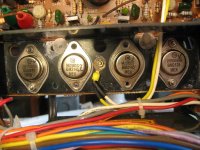
There is continuity between the case of TO3 output transistors and chassis ground when the mounting screws are in place, They are snug but not tight. At the moment, that continuity exists on the two TO3 in the center of the photo. Removing the mounting screws of those two middle transistors eliminates continuity. Even though mounting screws are in place, there is no continuity from either TO3 transistor at each end of the row.
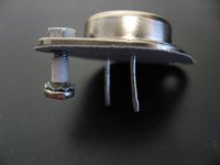
To me the fault would seem to be the plastic insulators used with the TO3's mounting screws. Some of the original insulators were salvageable and some were not. I have tried substitutes including small pieces of shrink tubing (as in the last photo) but so far nothing has worked to eliminate continuity with all of the TO3 output transistors when mounting screws are in place.
I have run out of inspiration so my question is....has anyone here needed to fabricate such an insulator and if so, what did you use?
Or, is there an online source for them and what are they called?
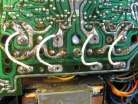
Yes, the trace side is messy and I will clean up the flux if/when I am done unsoldering/re-soldering.
EDIT: I suspect that this short of collector to base is why I cannot adjust idle current on either channel.
Firstly, I have re-used the mica/thermal paste insulators without success and now have sil pads in place - also without success. So I do not believe that is the issue.
Over the past two years I have picked away at problems with this receiver, including this one, numerous times. During that time, I think I corrected the other shortcomings but this one persists.
There is continuity between the case of TO3 output transistors and chassis ground when the mounting screws are in place, They are snug but not tight. At the moment, that continuity exists on the two TO3 in the center of the photo. Removing the mounting screws of those two middle transistors eliminates continuity. Even though mounting screws are in place, there is no continuity from either TO3 transistor at each end of the row.
To me the fault would seem to be the plastic insulators used with the TO3's mounting screws. Some of the original insulators were salvageable and some were not. I have tried substitutes including small pieces of shrink tubing (as in the last photo) but so far nothing has worked to eliminate continuity with all of the TO3 output transistors when mounting screws are in place.
I have run out of inspiration so my question is....has anyone here needed to fabricate such an insulator and if so, what did you use?
Or, is there an online source for them and what are they called?
Yes, the trace side is messy and I will clean up the flux if/when I am done unsoldering/re-soldering.
EDIT: I suspect that this short of collector to base is why I cannot adjust idle current on either channel.
Attachments
Last edited:
Search for TO-3 mounting kit. Here is one example: https://www.jameco.com/z/06-201-TEN...nt-Kit-for-TO-3-Packages-10-Packs-_34139.html
Have you tried using what I call 'proper' TO3 insulating bushes? Yours look more like bits of insulation over the bolt.

Gotta use insulating shoulder washers to insulate the bolts. Not just plain insulating washers or spacers.
https://www.digikey.com/en/products/detail/keystone-electronics/4698/316267
The Keystone washers are part of the kit Keystone sells for TO-3 mounting.
The Keystone washers are part of the kit Keystone sells for TO-3 mounting.
Attachments
I once considered those shoulder washers and even think I have some. But there were no such things in place originally. What was in place were short pieces of cylindrical plastic that only prevented the threaded section of the mounting screws from contacting the chassis.
The reason I did not try them is that I envisioned the shoulder, either insulating the mounting screw from the transistor case or preventing the transistor bottom surface from being flush with the mica or sil pad.
Dependant on if the washer's shoulder is on the top face of the transistor or the bottom face.
The machine screws for the TO3's are what connects their case/collector to the circuit board - the pads at one end of the white jumper wires in my 2nd photo.
But in the TO3 mounting kit, depicted in the link from Bill_P, I noticed the solder terminal and I may have some those too. Used in conjunction with a shoulder washer, I should be able to connect the case/collector to where the white jumper wires attach and keep the TO3's isolated from the chassis.
The first attempt using those shoulder washers was a fail. Continuity was still present between the cases of the two middle transistors and chassis ground. It was a frustrating outcome.
The only explanation that occurred to me was that somehow the threaded portion of the machine screws were shorting to the insides of the holes they passed through in the heatsink. I discovered that it was just one machine screw each of those two transistors that was shorting.
With nothing to lose, I enlarged the heatsink holes for those two transistors. That seems to have done the trick. The middle transistors are snugged down with their machine screws and the short is gone.
The two transistors at the ends of the row of four, were not problematic so I have left those alone. Shoulder washers and a "case jumper wire" were employed on the two middle transistors only.
I cannot put in much more than one hour per session with this receiver. Especially after dark. I need the natural light to see what I'm doing. Plus the 4' diameter dining table in my former residence where I performed such tasks seems spacious compared with my "work area" now. Sometimes the receiver was in my lap.
Tomorrow I will solder in the two output transistors I've been fiddling with then do a turn on using a DBT. If that does not disappoint, I'll try adjusting the idle which hopefully is now doable.
Recommendations here are wrong as they do not consider the fact that collector
connection to pcb is made via the screws in this model. Have a look at the second
picture. Isolating pads can be a problem also.
connection to pcb is made via the screws in this model. Have a look at the second
picture. Isolating pads can be a problem also.
Use the shoulder washers if it is the only good way to get isolation from the heat sink. Both screws on each transistor. But then you need to connect one of the little screw eye terminal jumpers to the collector pad on the PCB. That connection still doesn’t exist there, despite all the jumpers you have.
Looking at the solder joints in the photo.
Is also likely a solder bridge on the board.
Or direct short with all those extra wire leads.
The lower wire terminals look to be touching
or very close to touching another trace.
lots of flux and poor joints as well.
Is also likely a solder bridge on the board.
Or direct short with all those extra wire leads.
The lower wire terminals look to be touching
or very close to touching another trace.
lots of flux and poor joints as well.
Second picture :
- messy soldering at the driver(?) transistors, bent down wires, remove flux for inspection
- two missing transistors or like with three pins
- last picture : short to the long copper trace with added "case jumper wire" ?
- this wire is connected to the screw, not case, it seems,as seen in the picture before.
Yes, people, forget the top-hat insulating washers here, this is TO3, not TO220/TO247! The holes through the heatsink should be slightly countersunk/chamfered on both sides to prevent any burrs that might short to the screws - perhaps air-dust to remove any small shreds of metal that might have been shed.
The insulating bushes around the screws ideally are a hard plastic that doesn't get crushed/nipped when things are tightened up, nylon or PTFE are good choices, PVC is not.
But basically TO3 and similar packages have always been troublesome due to the lack of a pin for the case (what were the designers actually thinking, its such a silly omission), and the large opportunity for unintended shorts with the bare metal case. That's why its completely died out as a package style.
I am reasonably certain there is a proper connection from TO3 case to PC and that there is no case to chassis short,
My attention was directed elsewhere, to the power supply where I found a faulty transistor. A replacement is on order which I hope will restore idle adjustment which was what prompted this this TO3 short solving endeavour.
My attention was directed elsewhere, to the power supply where I found a faulty transistor. A replacement is on order which I hope will restore idle adjustment which was what prompted this this TO3 short solving endeavour.
- Home
- Amplifiers
- Solid State
- NAD 7225PE - need a method to isolate TO3 case aka collector from chassis ground