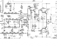
I'm trying to resurrect this old amp... one channel works fine, but the other distorts badly. I think I've tracked down the problem, but I want to ask for advice before replacing parts in a circuit I don't fully understand. (I don't have an online version of the schematic, but it's essentially the same as the venerable NAD 3020 and the like, as attached.)
After poking around with a scope, I think things are going wrong in Q601 -- everything looks fine on the base and emitter, but the signal at the collector is not good. I only get the lower half of the wave there, and it clips at a very low level as well.
So, am I safe in guessing that Q601 is shot? The voltage offsets everywhere match the notes in the service manual, more or less.
What sort of failure would cause this behavior?
Attachments
Hi Rob,
Have a look at C603and C605. They may be leaky. How is your DC offset on that channel?
Check C615 and C703 while you are there, I find 6.3 and 10V caps to be prone to failure. Replace them with 16V values on both channels.
-Chris
Have a look at C603and C605. They may be leaky. How is your DC offset on that channel?
Check C615 and C703 while you are there, I find 6.3 and 10V caps to be prone to failure. Replace them with 16V values on both channels.
-Chris
anatech said:Hi Rob,
Have a look at C603and C605. They may be leaky.
To the extent that I can test them, they seem fine. I'll try replacing them (not a bad idea anyway, I guess) and see if that improves things.
How is your DC offset on that channel?
Offset at the speakers is 22 mV on the bad channel and 24mV on the good one.
Check C615 and C703 while you are there, I find 6.3 and 10V caps to be prone to failure. Replace them with 16V values on both channels.
Will do. Thanks for the advice!
-- Rob
Does the base and emitter voltages track i.e. follow eachother (with gain)?
It seems the collector is the feedback node of the input and therefore it is hard to determine why the signal looks like crap there, a failure in any other transistor following the q601 might cause this.
You are saying that the DC points look fine, have you checked the -26V point. The powersupply seems prone to failure in these.
hjelm said:Does the base and emitter voltages track i.e. follow eachother (with gain)?
Yep.
You are saying that the DC points look fine, have you checked the -26V point.
Yep. It's where it should be.
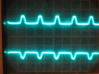
I also looked at base of Q605 and the base of Q607 (top trace is Q607 -- and that's supposed to be a sine wave). Anything else I should check?
Attachments
Is there any current across R629?
What levels does the scope image represent, i.e. at what level is the flat line and how high are the peaks, and for which input ac voltage?
Try to adjust the vr601 slightly and see if the signal improves, think it sets the bias for the input. Check if the trimpot is broken.
What levels does the scope image represent, i.e. at what level is the flat line and how high are the peaks, and for which input ac voltage?
Try to adjust the vr601 slightly and see if the signal improves, think it sets the bias for the input. Check if the trimpot is broken.
By chance is the 1 ohm resistor open in the collector of the MJ2955. I have seen techs forget to resolder the bridge to short this resistor out. The only time the resistor is not shorted is to set bias (with no load). It is a 1/4W device.
-Chris
-Chris
More clues
I replaced all the electrolytic caps in the bad channel, just to rule that out as a possibility, but it didn't solve the problem.
I've noticed some very strange symptoms, though. Across R637, the -38V rail (the 7130 is slightly beefier than the 3020) is supposed to drop to about -15V. Instead, on the bad channel it drops to -5V for 1 second, then to -15V for 30 seconds, and then it shifts to -7V and stays there. Across R649, that -15V is supposed to drop to -1.1V at the base of Q613. Instead it goes to +16V for 1 sec, falls to 0V, then it looks like it starts oscillating at 60Hz, followed by gradually increasing oscillation beyond what I can make out on my salvaged-from-the-trash 15MHz scope. After about 30 seconds of that, the DC offset there goes back to +16V. Oh, and, there's no C631 on this particular model.
Any ideas?
Hi Rob,
Did you check if R659 is shorted by a solder bridge (it should be)? If not, R659 is open and you have no -29V on the collector of Q617.
-Chris
Did you check if R659 is shorted by a solder bridge (it should be)? If not, R659 is open and you have no -29V on the collector of Q617.
-Chris
anatech said:Did you check if R659 is shorted by a solder bridge (it should be)?
The idle-current-checking resistor is on the positive rail on this one, and it is shorted. And, I just checked, the collector of Q617 has a nice steady -31V, as it should.
Thanks for the suggestions, though! I can use all the help I can get.
Hi Rob,
What are the DC conditions around Q601 aqnd Q600? Q600 is supposed to be an adjustabke constant current source. Also,how close is this unit to the schematic?
Are you injecting a signal in the normal in? What is the amplitude of your test signal? Track it from the input terminal to the collector of Q601 & let us know what you get. Try pulling C603 to disconnect that circuit. I've had leaky diodes do weird things.
-Chris
anatech said:Hi Rob,
What are the DC conditions around Q601 aqnd Q600? Q600 is supposed to be an adjustabke constant current source. Also,how close is this unit to the schematic?
Are you injecting a signal in the normal in? What is the amplitude of your test signal? Track it from the input terminal to the collector of Q601 & let us know what you get. Try pulling C603 to disconnect that circuit. I've had leaky diodes do weird things.
-Chris
This model doesn't have a lab input (I'll try to get to a scanner at work next week so I post the real schematics). The input signal shows up at the base of Q601 looking fine, about 40mV p-p. The DC bias at the the base of Q601 is about 1.1V and it's at about 0.5V at the emitter. According to my notes, the bias around Q600 is about +38V everywhere -- I'll try to measure that more accurately tomorrow.
Something odd I've noticed: at the base of Q100 on the bad channel (but not the good one), there's a reduced, out of phase, distorted version of the signal. There's no signal at D603 (other than what sneaks in on the postive rail (and that's the same on both channels)). so I guess it has to be getting there through Q100, right?
What is the voltage around D601? It should read + 0.5-0.7V relative to ground, anode side.
Does R607 have ~4.8V across it, would indicate that the bias for the current generator is working.
Measure across R629(or what it reads on the emitterresistor of the Q600 can't read it) The bias should probably be a few mA and this would be ~39-390mV (1-10mA).
If you could scribble all measured DC voltages on the schematic around the active components and diodes. Would help its hard to visualize otherwise.
Happy hunting.
I agree to anatech's hint that there might be something wrong with the current source formed by Q600 and it's resistor/capacitor/diode-network. If you measure the voltage drop across R629, corresponding with any reasonable DC bias of Q600.
You could compare the DC drop across R629 with the relevant DC drop in the second chanel.
My guess is that the defect chanel does show nearly no voltage drop across R629. So Q600 would be not active and could not pull upwards the base of Q605.
If you are facing a missing DC bias of Q600 (you can also check the Vbe of Q600 itself), then carefully compare the voltage drops across the resistors, capacitors and diodes R623, R621, R605, R607, R609, R611, R613, VR601, D601, D603, C611 with the working chanel. Hopefully you will find the reason there. May be C611 is leaking and by this shortening the base bias of Q600.
Good Luck
Markus
Hi Rob,
Okay, Q601 is forward biased but there is no current flowing through the collector. Q600 may be turned off depending on the E-B drop. If Q601 was defective you may get this situation. Knowing that you have +38V at Q600 collector (Q601 collector and Q605 base), you should have no current (Q605 is off) through Q607, 611 and 615, also no bias current. Check Q601 out of circuit. Also check Q600 for a C-E short just in case.
-Chris
- Status
- Not open for further replies.
- Home
- Amplifiers
- Solid State
- NAD 7130 troubleshooting