Hi All,
I popped open my NAD 522 CD player, and have obtained the data sheets etc. for the DAC and DSP chip involved. I wish to add a digital output to this player, and am wanting advice as to how I should go about this. Warning - I am very much a newbie when it comes to this type of stuff, but I am willing to learn.
They chips involved are the Burr Brown PCM1710U DAC chip and the Sanyo LC78621 DSP chip .
It appears that the DSP chip is configured for CD-ROM output type (No oversampling etc. performed by the DSP) as it is outputting to the DAC via pins 42-44 (LRSY, CK2, ROMXA).
The DSP chip has pin 56 on it as DOUT. Data is output according to the data sheet above in EIAJ format. It has a built-in driver circuit and can directly drive a transformer. I don't know if this pin has been enabled or not - could I check this using a scope? Could this pin be used to obtain the digital out I require?
Any help you could give me would be fantastic.
Thanks very much,
Jonathan
yes, you can check it with the scope. Just play something and check if there is any signal (it should have 5V amplitude) on that pin. If DOUT is enabled you can easily use this pin to directly drive digital transformer (it should have 5:1 ratio for SPDIF), but maybe you would be better to install dedicated drive circuit (search this forum for schematic).
Jonathan,
I am 99.5% sure dout on the "LC78621 DSP" chip will work the way you want and if you have a scope to verify....great..... if not just go ahead.....
Michael
I am 99.5% sure dout on the "LC78621 DSP" chip will work the way you want and if you have a scope to verify....great..... if not just go ahead.....
Michael
Maby you can connect to your dout a buffer (hexconverter)
for more info check:
http://www.epanorama.net/documents/audio/spdif.html
Code:
                            |\
                      +-----| O-----------+
                      |     |/            |               S/PDIF output
                      |                   |  150nF        (RCA or BNC)
             |\       |     |\            |   ||
TTL level ---| o------+-----| O-----------+---||-----374R---+----- center pin
signal       |/       |     |/            |   ||            |
                      |                   |                 |
                      |     |\            |                93R1
                      +-----| O-----------+                 |
                      |     |/            |                 +----- ground
                      |                   |                 |
                      |     |\            |                ---
                      +-----| 0-----------+
                      |     |/            |
                      |                   |
                      |     |\            |
                      +-----| 0-----------+
                            |/

                          74HTU04
for more info check:
http://www.epanorama.net/documents/audio/spdif.html
Thanks for the replies...
Thanks all for the speedy and informative replies.
I think I will first implement the simplest circuit shown on epanorama.net first just to see if the DOUT pin is enabled or not.
Assuming this works (It should - the DOUT pin should have enough current to drive this as it can drive a transformer according to the data sheet), what would be the best way to proceed?
I wish to have the best connection I can - galvanic isolation would be good too (so as to avoid ground loops). Any suggestions on which setup would be "best"??
Thanks again,
Jonathan
Thanks all for the speedy and informative replies.
I think I will first implement the simplest circuit shown on epanorama.net first just to see if the DOUT pin is enabled or not.
Code:
         100nF
  TTL ----||-----330ohm--+--------- coax S/PDIF signal out
  in                     |
                      100ohm
                         |
 Ground -----------------+--------- coax signal ground
Assuming this works (It should - the DOUT pin should have enough current to drive this as it can drive a transformer according to the data sheet), what would be the best way to proceed?
I wish to have the best connection I can - galvanic isolation would be good too (so as to avoid ground loops). Any suggestions on which setup would be "best"??
Thanks again,
Jonathan
OK - I got it all going 🙂
I tried the schematic in my last post (The REAL simple one), and sure enough, it works great!
I haven't had a chance to have a decent listen yet to see if I can hear a difference between the analog and digital outputs (The DAC on the digital output are the ones in my NAD T752 receiver)
Was fairly easy to hook up - the only tricky bit was soldering to the DOUT pin (Pin 56 in case someone else wants to give it a go) as the SMD component has small feet. Luckily all went well. I took the digital ground off a jumper wire.
Now I just need to finish things off - Attach connector etc. to back panel + stuff.
Any ideas on how I could improve things over this real simple circuit??
Thanks for all your help and advice.
Cheers,
Jonathan
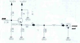
A 8 said:You could try this.
Add better de-coupling ex oscon >100u, MKP/MKT and ceramics NPO, loose the coil and parallel a few HQ MKP-foil caps on the output and you should have a nice drive circuit.
Hi
This cicruit does not look very promissing
- It does not show 75 ohm source impedance
- It is too asymetrical
I suggest the use of reclocking, drive with 75 ohm and please use a transformer before leaving the CD players' cabinet
succes
Hi
This cicruit does not look very promissing
- It does not show 75 ohm source impedance
- It is too asymetrical
I suggest the use of reclocking, drive with 75 ohm and please use a transformer before leaving the CD players' cabinet
succes
In all honesty I have not tested it, found it in a commercial high end dvd-player superior to a player based on the same circuits except this buffer stage.
Either way I agree with Guido that the best you can do is to re-clock dout before you buffer.
Output impedance......
It might be close to 75 ohms, by the time you take into account the impedance of the follower. Still, doesn't look that promising.
Make sure the transformer can actually pass a square wave at SPDIF frequencies. A lot of the ones that I have seen in CDPs are too low in bandwidth to be useful. Good for keeping EMI down, but they sound dreadful.
Jocko
A 8 said:
In all honesty I have not tested it, found it in a commercial high end dvd-player superior to a player based on the same circuits except this buffer stage.
Either way I agree with Guido that the best you can do is to re-clock dout before you buffer.
Hi A8
I overlooked your remark to take out the choke, ofcourse that makes it much better, but still.....
Not knowing the value of the choke....
It might be there to build out the impedance to compensate for the excessive capacitance of the RCA jack.
(Stop giving away Phred's secrets..........!)
But probably not. Probably to limit EMI.
Jocko
It might be there to build out the impedance to compensate for the excessive capacitance of the RCA jack.
(Stop giving away Phred's secrets..........!)
But probably not. Probably to limit EMI.
Jocko
- Status
- Not open for further replies.
- Home
- Source & Line
- Digital Source
- NAD 522 CD Player Digital Out Mod - HELP!