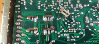
ok so all fitted and ,it doesnt work, just a load of static noise from the volume control, sim going to have to have a look and see whats up.
The boards look good visually but yes, thinks look fine and small when you see them for real. I like thick traces and large pads for through hole stuff.
As Mooly says, the board looks basically ok - the track sizes are more than adequate for the current requirements, but thicker/wider indeed reduces impedance more. I can't see any obvious reason it shouldn't work. In the mean time, I assume you've fitted R401 & the jumper wire, and that all 6 connection tabs are soldered to the relevant tracks on the main NAD PCB, and that the phono input sockets on the amp are wired +ve & gnd to the main PCB, so they hook up correctly to the new PCB.
I'd also add solder to the thru' holes on the connection tabs, otherwise you're relying only on the thru' hole plating for the electrical connections.
I'd also add solder to the thru' holes on the connection tabs, otherwise you're relying only on the thru' hole plating for the electrical connections.
one thing i did notice was the cap on the input is round the wrong way, but i spun that and it didnt make any difference
not easy to check while the board is in place so im going to run some wires out so i can check it on the mat
You can test it properly out of the amp by running it from your power supply and feeding a known good signal from the generator into it.
Remember the input level will be only a few millivolts. Use a simple two resistor attenuator such as a 1k and 10 ohm and feed it with a volt or so of signal @ 1kHz and take the signal for the preamp input from across the 10 ohm.
Remember the input level will be only a few millivolts. Use a simple two resistor attenuator such as a 1k and 10 ohm and feed it with a volt or so of signal @ 1kHz and take the signal for the preamp input from across the 10 ohm.
Another potential pitfall might be the transistor pinouts vs. the pcb / circuit, maybe worth checking that they're all correct for the pcb.
Maybe also worth checking the main pcb & wiring to ensure that the phono amps are properly connected into the source selection switch, preamp, etc., e.g., might the previous owner have changed anything else when he removed the original phono amp boards...?
Maybe also worth checking the main pcb & wiring to ensure that the phono amps are properly connected into the source selection switch, preamp, etc., e.g., might the previous owner have changed anything else when he removed the original phono amp boards...?
rigged it up to the external power supply and i couldnt get Q401 to turn on, so i checked the transistor and it was a BC547 (NPN) must have got mixed up in the pack,so its all working ok.Now onto do the other channel.
👍
Just for completeness - there are no extra wire connections going to points 47, 48, 49, or 50, or 51. Jumpers J13 & J20 are both present (close to #51). The phono input sockets are hardwired with screened cables to points 33 & 35, and 34 & 36. All other connections are via the six connection 'tabs' on the new pcb's (photo below is my original set-up).

Just for completeness - there are no extra wire connections going to points 47, 48, 49, or 50, or 51. Jumpers J13 & J20 are both present (close to #51). The phono input sockets are hardwired with screened cables to points 33 & 35, and 34 & 36. All other connections are via the six connection 'tabs' on the new pcb's (photo below is my original set-up).

- Home
- Amplifiers
- Solid State
- NAD 3030 complete rebuild