Hello gays
I want to rebuild a NAD 3020 first series.
Can you help me for 4 big transistors position Base- collector.
Thank you.
I want to rebuild a NAD 3020 first series.
Can you help me for 4 big transistors position Base- collector.
Thank you.
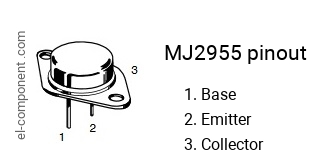
The collector terminal is always the case for a TO-3, so you can use a meter
to determine the base and emitter pins, if necessary.
2N3055 Datasheet Archive 2N3055 datasheet download
2n2955 Datasheet Archive 2n2955%20to3 datasheet download
to determine the base and emitter pins, if necessary.
2N3055 Datasheet Archive 2N3055 datasheet download
2n2955 Datasheet Archive 2n2955%20to3 datasheet download
Last edited:

Ok.for exemple.
First left transistor.
Left pin E or B
Second transistor left pin E or B
And so on ....
My 3020 is without transistors......
First left transistor.
Left pin E or B
Second transistor left pin E or B
And so on ....
My 3020 is without transistors......
Last edited:


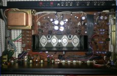
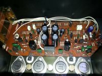
If you align the transistors in the same direction as the photos, you don't need a lecture, schematic or anything further. There are only 2 options for each transistor and the markings on each transistor, as well as the position of the holes in the PCB show whether each transistor is oriented either up or down (as shown in pics).
It's nearly impossible to get that wrong, unless of course, you can't see the pics. or the schematics. Try here: NAD 3020A Schematic These from Plant 10 are actually f...you want to hear the original product by DIY.
It's nearly impossible to get that wrong, unless of course, you can't see the pics. or the schematics. Try here: NAD 3020A Schematic These from Plant 10 are actually f...you want to hear the original product by DIY.
Last edited:
They will only fit one way as the pins are offset
There are newer transistors available 2n6443 I think
There are newer transistors available 2n6443 I think
The hard part though, is that the original 2N3055 transistors are different (hometaxial) to all that are available now, 40 years later (epitaxial)..
Wikipedia states that also the 2N3055 was later produced as epitaxial:
2N3055 - Wikipedia
" It was introduced in the early 1960s by RCA using a hometaxial power transistor process, transitioned to an epitaxial base in the mid-1970s."
?
All 4 power transistors are replaced by original Motorola.
BD 139 also replaced.
Now amplifier power on,all 4 fuses OK.
But the sound on 2 channels is low and distorted.
BD 139 also replaced.
Now amplifier power on,all 4 fuses OK.
But the sound on 2 channels is low and distorted.
Last edited:
I would start with getting the power amplifier stage into working condition (or verifying that it is working OK).
Before doing the basic forenzics (DC voltages, sine signal on scope) I would replace the tantalum capacitors in the signal path:

C601...C604.
After that I would feed signal to "NORMAL IN" i.e. input of the power stage from another device (preamplifier, computer sound card etc) that I know to be in working condition.
Once you get the power amplifier stage working OK then you ca start with the preamplifier section.
Before doing the basic forenzics (DC voltages, sine signal on scope) I would replace the tantalum capacitors in the signal path:
C601...C604.
After that I would feed signal to "NORMAL IN" i.e. input of the power stage from another device (preamplifier, computer sound card etc) that I know to be in working condition.
Once you get the power amplifier stage working OK then you ca start with the preamplifier section.
I would replace the tantalums in signal path anyway (unless the goal is to keep the amp as close to its original state as possible) 😉
They only fit in one way !
The two pins underneath are offset if you look.
Note insulators only fit right one way too.
I bought in a 2n3055/mj2955 Maplin amp to repair.
I replaced 2n3055/mj2955 with modern versions with same number and the amp oscillated.
I can only guess new transistors had more gain or a wider bandwidth.
I had to increase the VAS capacitor to stop the oscillation.
Last edited:
- Home
- Amplifiers
- Solid State
- NAD 3020 transistors position.