Hi oggioffshore,
Yes, you washed out the conductive debris that was shorting the commutator at that point. The brushes are worn, so it may fail later (expected). See if you can find another motor that you can install at a later date when you need it.
The fix is not permanent, although I really wish it was. If you get a long time out of it - GREAT! You did fix the immediate problem.
-Chris
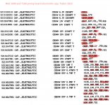
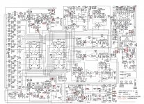
I made a list of the electrolytics on the 1600 preamp board. The service manual is a very bad scan, so I used the one in the 7100, that has exactly the same preamp board. It was nice to spend some time reading the schematic. Next I will do the tone board. The list gives me an undertanting of the caps used and their values.
One thing that call my attention is that there are no power decoupling caps on the 18.5V rails to the NJM 2043D ( three in this board). I always read that this is a bad practice. Should this be amended by adding decoupling caps, ceramics 100nf? The NAD 18V power supply/ rectifier has two 100 nf out he output (C533, C50) , but no decoupling on the opamps. I found this short article in TI https://e2e.ti.com/blogs_/archives/...e-decoupling-capacitor-is-it-really-necessary


One thing that call my attention is that there are no power decoupling caps on the 18.5V rails to the NJM 2043D ( three in this board). I always read that this is a bad practice. Should this be amended by adding decoupling caps, ceramics 100nf? The NAD 18V power supply/ rectifier has two 100 nf out he output (C533, C50) , but no decoupling on the opamps. I found this short article in TI https://e2e.ti.com/blogs_/archives/...e-decoupling-capacitor-is-it-really-necessary
Attachments
Last edited:
You know, many times electrolytic capacitors are not in areas where they are stressed and you really are better off leaving them alone. As far as decoupling is concerned, be very, very careful. You are coupling supply noise into a ground path. So without very careful consideration you can easily make things much worse. What flows in the ground (REFERENCE) is critical so watch out.
I always asked new technians, "when is a ground not a ground?". Because there is reactance, one ground point isn't the same as another at high frequencies. So you have to choose very carefully. In sensitive equipment we have what is called a "dirty ground", signal ground and other general purpose ground paths. They do connect in the power supply (usually), but they are totally separate things!
Things are not that simple no matter how they appear to be in some cases.
As of now I am on a work trip and I will not be able to do anything for another month. Just gathering info about how to better refurb the nad 1600
I was making the list of electrolytics as a way to identify them, mostly to get familiar with the schematic before even considering making any changes. Now i can look at the caps in the board more closely and see if any is dammage/ discolored. I already have decided against changing caps unless damaged.
Some of the caps that are connected around the power rails (18.5V) have very low ratings (6.3V). The only ones that might be stressed, other than those, my guess, might be on the power supply. There are a couple on the board that look discolored, and both are very close to the dissipators of some transistors.
Now I am confused. I was under the impression that in the band that audio works was considered low frequency. I am aware about high frequency interference and that radio interference filtering is present in pro equipment.
Regarding the decoupling caps, I was planning to connect them to an existing ground path in the same block where the IC as located (such as using the ground points after R269 and R270 in Q211 for the decupling caps for V+ and V-, see pic in my prior post) . My understanding of the schematic, other what are the main blocks and what is their purpose , is very limited. I never considered the possibility that picking the wrong gnd point would make things worst. Will pass on "improving" the circuit.
But I was very surprised that a competent design was not following a design principle, decoupling the V+ and V- of the IC, that stated as a must in many datasheet and application notes.
I was making the list of electrolytics as a way to identify them, mostly to get familiar with the schematic before even considering making any changes. Now i can look at the caps in the board more closely and see if any is dammage/ discolored. I already have decided against changing caps unless damaged.
Some of the caps that are connected around the power rails (18.5V) have very low ratings (6.3V). The only ones that might be stressed, other than those, my guess, might be on the power supply. There are a couple on the board that look discolored, and both are very close to the dissipators of some transistors.
anatech said 'I always asked new technicians, "when is a ground not a ground?". Because there is reactance, one ground point isn't the same as another at high frequencies. So you have to choose very carefully. In sensitive equipment we have what is called a "dirty ground", signal ground and other general purpose ground paths. They do connect in the power supply (usually), but they are totally separate things!'
Now I am confused. I was under the impression that in the band that audio works was considered low frequency. I am aware about high frequency interference and that radio interference filtering is present in pro equipment.
Regarding the decoupling caps, I was planning to connect them to an existing ground path in the same block where the IC as located (such as using the ground points after R269 and R270 in Q211 for the decupling caps for V+ and V-, see pic in my prior post) . My understanding of the schematic, other what are the main blocks and what is their purpose , is very limited. I never considered the possibility that picking the wrong gnd point would make things worst. Will pass on "improving" the circuit.
But I was very surprised that a competent design was not following a design principle, decoupling the V+ and V- of the IC, that stated as a must in many datasheet and application notes.
Last edited:
Things are not that simple no matter how they appear to be in some cases.
Few other points;
1) "ground" refers to a completely arbitrary voltage and is in no way magical or special
2) it does not take a very high frequency before ground planes can do more harm than good.
3) a very good note is https://www.analog.com/media/en/technical-documentation/application-notes/AN-202.pdf - especially the part "The Other Input" toward the end.

I purch'd this unit new in early 90s. Very problematic from get go. Sent in for service a year or two after purch. Had ongoing issues with tuner memory . Sound quality was decent. Very messy layout inside -- difficult to do maintenance. Replaced many electro caps -- 7 years or so ago -- and eBay'd. Miss the tuner and remote. But otherwise: good riddance!
"Good for the money"
That's what the deal was in the industry. No firther comment as it isn't helpful to the thread.
That's what the deal was in the industry. No firther comment as it isn't helpful to the thread.
I replaced the power supply caps for Nichicon UPW 2200uf, twice the value at 50V also. They fit perfectly within the existing holes on the board. The old ones looked damaged with puffed tops . After removing them and measure them, the capacitance was right on the spot, about 1000uf . I also had to replace a switch I accidentally broke while cleaning the unit.

All the pots and switches are perfect, feel good with no noise. All the controls from the board work. An imbalance between the channels has disappeared now and the unit is very clean sounding, you have to raise the volume to the above the maximum input level of the amp (the amp will go into protection) to hear crosstalk. Most of the buttons on the remote control trigger actions on the unit, but the motorized pot is not responsive. I am curious on how it measures, looking for an audio interface now.
I got a nice 20000 counts tester, a UNI-T UT161E and looking for an analog scope.
The unit in all lights configuration. It is also connected to a sl1200Mk2 that I refurbished last year.
With High Frequency, are you referring to external rf interference or internal operational frequency?2) it does not take a very high frequency before ground planes can do more harm than good.
I have only designed board for low frequency digital (microcontrollers and daughterboards). I can see that nowadays most audio boards still lack ground planes (even some are one layer) but it seems that the rest of the electronics industry has moved to multilayer (4 or more) with stitching between ground planes.
The G word by Bruno Putzeys (Purify, ex Hypex) is a great article about ground and audio.
over one year since the last post, unit is happy and working with no problems. I have taken it out as I am testing another preamp. Just took a look inside and all looks good.
I took a look at all the caps, and the ones on the signal path look good. the ones on the power supplies (+- 18.5, +- 25, +15, +5) do not look so good. Going to check the voltages and see how the look on the scope.
The power supply capacitors are typically going to be your problem. Signal path capacitors have an easy life, so it they are decent quality, no problem.
Still going down the rabbit hole. Learning the schematic and checking all the different supplies (+-32 unreg, +- 24 reg, +-18 reg, +-18.5 reg, +5, +12). I've order a esr tester to check one of the cap in the 15V regulator. The other voltages seem ok. The all the dual voltage regulators only use transistors).
The unit has 3 diode bridges, one for the transformers that acts as the input caps for all the others, and then two three blocks 4 1n4148 and 4 1n4002 (8 diodes between both). The diodes are used for the 15 and 5V lines.
People say these units have crappy caps, but I can see a lot of elna and other nice brands.
Seems that the +5V (7805) is used for the logic and the +15V(7815) for the motorized pot and other uses.
The motorized pot was non operative. After checking the voltages of the H-bridge Toshiba bridge, I decided to touch the solder points of the motor. One of them did not look good. After reflowing the moto pot came back and now it works. The remote control is kind of clunky but I use an universal and I have used the learning via the app.
unregulated +- 35V

regulated +-18V and +- 24V ( for the audio electronics)

+- 18.0 V for the headphones

+5 +15V on another board.

The unit has 3 diode bridges, one for the transformers that acts as the input caps for all the others, and then two three blocks 4 1n4148 and 4 1n4002 (8 diodes between both). The diodes are used for the 15 and 5V lines.
People say these units have crappy caps, but I can see a lot of elna and other nice brands.
Seems that the +5V (7805) is used for the logic and the +15V(7815) for the motorized pot and other uses.
The motorized pot was non operative. After checking the voltages of the H-bridge Toshiba bridge, I decided to touch the solder points of the motor. One of them did not look good. After reflowing the moto pot came back and now it works. The remote control is kind of clunky but I use an universal and I have used the learning via the app.
unregulated +- 35V
regulated +-18V and +- 24V ( for the audio electronics)
+- 18.0 V for the headphones
+5 +15V on another board.
Hi Frabor,
Elna are not always good. Also, do not buy an ESR tester, those are a complete waste of money. You want to measure DA at different frequencies. This is a much more sensitive measurement
So why are ESR testers so popular? The concept is easy to understand and they are cheap. That's it. You can get a decent cap checker for electrolytics at AliExpress for less than $100 Canadian (metal case too!), and it measures ESR as well. The resolution is only good enough to show cheap as heck film caps. To get better resolution you are into much more expensive instruments.
tks, will go back, wonders of the big river. thought it would be a nice addition to the test kit, and it was only 50 usd.
lol!
That tells you a great deal right there. Good LCR meters cost well over $2K when they have reasonable accuracy. The LCR meter I found on AliExpress surprised me for the money. I bought one because it is small and portable, unlike my three huge bench meters that are worth too much to cart around. I do check the little thing's performance against my "real" instruments. It performs well enough if you keep it's accuracy in mind. That is pretty good by the way.
That tells you a great deal right there. Good LCR meters cost well over $2K when they have reasonable accuracy. The LCR meter I found on AliExpress surprised me for the money. I bought one because it is small and portable, unlike my three huge bench meters that are worth too much to cart around. I do check the little thing's performance against my "real" instruments. It performs well enough if you keep it's accuracy in mind. That is pretty good by the way.
Below is a link of a discussion of the ESR meters. It generates a 100kHz signal and measures the resistance. Several video on YT defines the device as a in-circuit failed capacitor validator. After the reading, there is a table of worst case esr estimates. If your cap is very close or over this threshold, time to remove it and tested outside. It is never supposed to be a certification instrument to know the ESR, just a device to tell you fail or not fail (not a pass).
These are the claims of the users, and I would have been great if you could use it like that.
https://www.eevblog.com/forum/testgear/new-esr-meter-mesr-100-v2-by-_jingyan_/

These are the claims of the users, and I would have been great if you could use it like that.
https://www.eevblog.com/forum/testgear/new-esr-meter-mesr-100-v2-by-_jingyan_/
Hi Frabor,
An ESR meter only gives you the most basic information. 100KHz is too high for many capacitors. THey should be measured in the frequency range they will see. So power supply capacitors around 100 Hz (they see 120 Hz in North America). Audio tests at 1 KHz and 10 KHz. At 100 KHz, the lead inductances and stray capacitance becomes significant, so a cheap tester that operates at those frequencies? I have sincere doubts they will test in any reasonable way.
Check this out ...
https://www.aliexpress.com/item/329...o.order_list.order_list_main.4.9c891802pACfy8
The prebuilt one with both kelvin and tweezers is $94.49 Canadian. You'll probably at least want the Kelvin test leads as a minimum, you need to test capacitors and inductors with Kelvin leads. The tweezers are Kelvin for surface mount.
I have recommended these to local techs who played with mine. They bought them and are pretty happy. I don't get anything from this, but don't waste your money on an ESR meter.
-Chris
Just to throw this out - the Instek LCR-6100 is the exact same unit as the Teledyne LeCroy T3LCR1100 at about half the price. I have one and it is a very nice unit - basic accuracy of 0.05% at up to 100KHz. Not cheap but a very good value for the features and performance it has.
https://www.tequipment.net/Instek/LCR-6100/LCR-Meters/
https://www.tequipment.net/LeCroy/T3LCR1100/LCR-Meters/
https://www.tequipment.net/Instek/LCR-6100/LCR-Meters/
https://www.tequipment.net/LeCroy/T3LCR1100/LCR-Meters/
- Home
- Amplifiers
- Solid State
- NAD 1600 Recap, list of caps?