Hi all, this is probably a very dumb questions but some creative googling couldn't tell me exactly how dumb of a question it is.
I got some cheap VU meters for free, and wanted to test them. So, I set my phone to output a 1kHz sine, hooked it through a pre-amp, made sure the output was about 1.23VAC RMS (checked with my multimeter) and connected the VU meters. Right now meters should be showing 0dBu, right? Of course not, because the sum of that sine is 0. So I stuck a 1N4148 in there, and the needle is indeed moving now 🙂
However - how do I now calibrate the meter? There's going to be a voltage drop across that diode.
Sorry if this is a stupid question!
Its a good question. As you have found out, the meter only responds to DC and so needs some means of rectifying the incoming audio. The silicon diode loses an awful lot of voltage across it (around 500mv at really low levels) and so its not a good approach.
A germanium diode is better (around 120mv lost) but better still is a proper meter drive circuit.
Ideally you want the circuit to 'hold' the peaks a little such that the meter has time to respond and also if possible to remove the diode volt drop. That can be done by including the diode in the feedback loop of an opamp.
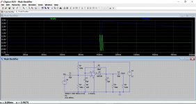
Look at this. The input is a short tone burst of just a few cycles. The output is a DC voltage that rises quickly and decays slowly.
A germanium diode is better (around 120mv lost) but better still is a proper meter drive circuit.
Ideally you want the circuit to 'hold' the peaks a little such that the meter has time to respond and also if possible to remove the diode volt drop. That can be done by including the diode in the feedback loop of an opamp.
Look at this. The input is a short tone burst of just a few cycles. The output is a DC voltage that rises quickly and decays slowly.
Attachments
Keep in mind there is "VU Meter" the piece of equipment, and it responds as you expect. Then there is VU Meter the component, a meter movement with VU scale printed on it for use in a circuit to indicate volume level. It is used in the piece of equipment. The meter part itself is not calibrated to indicate VU from direct connection to the audio.
Thanks very much for your responses. I was a bit naive to expect the meter would respond directly to what is 0dBu.
I have some reading and experimenting to do but I'll get there 🙂
I have some reading and experimenting to do but I'll get there 🙂
OK 🙂
If you want a simple VU meter type circuit then have a look at some old cassette deck service manuals such as Sony TCK5 and TC136SD etc. Look how they do it.
If you want a simple VU meter type circuit then have a look at some old cassette deck service manuals such as Sony TCK5 and TC136SD etc. Look how they do it.
An old application note for a led VU meter ..but also a lot of information on level meter use ..
http://www.experimentalistsanonymous.com/diy/Datasheets/LM3915.pdf
http://www.experimentalistsanonymous.com/diy/Datasheets/LM3915.pdf
An old application note for a led VU meter ..but also a lot of information on level meter use ..
http://www.experimentalistsanonymous.com/diy/Datasheets/LM3915.pdf
That has one of the things I was thinking of - a "precision" rectifier.
basically using an op amp you can make a diode with no forward voltage drop.
A proper VU Meter has a Copper-Oxide full-wave bridge and a resistor inside.
The "VU marked" meters you got are poor imitations and will need some work. Si diodes eat half the scale. Ge some better. Schottkey may be better? But none of the "modern good" rectifiers have the near-Zero conductivity of copper-oxide.
The true VU meter is very sensitive and highly damped. VU-marked meters typically use much more power (heavy loading on circuit), and flap excessively.
"Driver circuits" may reduce some of these problems.
A proper VU Meter has a Copper-Oxide full-wave bridge and a resistor inside.
The "VU marked" meters you got are poor imitations and will need some work. Si diodes eat half the scale. Ge some better. Schottkey may be better? But none of the "modern good" rectifiers have the near-Zero conductivity of copper-oxide.
The true VU meter is very sensitive and highly damped. VU-marked meters typically use much more power (heavy loading on circuit), and flap excessively.
"Driver circuits" may reduce some of these problems.
And so is my 'problem'.... can't seem to find a < 0.3V Scottkey rated at least 150V [250W into 8 Ohm load]
I suspect peak [ or even worst case clip] speaker voltage is too problematic for use as passive VU meter drive circuits.
A VU meter should never see over about 13V music peak.
If you have 150V, you need an attenuator in front.
If you have 150V, you need an attenuator in front.
Passive log driver circuits I'v seen and raised in other VU threads cite breakdown voltage of diodes [input signal rectification] no problem for small output amps [below 100W rating].
Input signal to driver boards with opamps look to have current limit resistors and Cap in input to opamp. Likewise in passive circuit using diodes rectify input along with series resistor > 100K and diodes/resistors between output line and ground [feeding speaker] to tune output curve to close to log . Need to find thread and link to post here and explains problem I have with higher output amp.
I think for all the bother, better off without dancin needles.... mounted on an active sub. Any moving coil movement has a probable short life anyway with all that vibe.
- Status
- Not open for further replies.
- Home
- Design & Build
- Equipment & Tools
- [n00b question] Please help me understand testing VU meters