Hello dear DIY'ers,
I am looking for a working N-Channel mosfet amplifier schematic.
I looked into several threads, but didnot manage to find a complete schematic which is operative.
All schematics (with one or more mosfet pairs in the output stage are OK).
You can use my mail adress.
Thank you in advance:
Nexus
🙂
I am looking for a working N-Channel mosfet amplifier schematic.
I looked into several threads, but didnot manage to find a complete schematic which is operative.
All schematics (with one or more mosfet pairs in the output stage are OK).
You can use my mail adress.
Thank you in advance:
Nexus
🙂
What quality level are you looking for?
Hifi or PA?
How much power is needed?
I intend to publish a new N-channel design shortly.
Best regards
Lars Clausen
Hifi or PA?
How much power is needed?
I intend to publish a new N-channel design shortly.
Best regards
Lars Clausen
In the JLH 10w Class A thread is a N-channel version which can be run in class B without modification.. it is a working design and it is build by me and another forum member... but also N Pass citation 12 mosfet version ... and some more which have not been build yet but have been simulated only so far...
goodluck
PS
Looking forward to your design Lars😎
edit
And offcrouse how could I forget.. X-pro's design... that's a real nice one.. look for x-pro posts...
goodluck
PS
Looking forward to your design Lars😎
edit
And offcrouse how could I forget.. X-pro's design... that's a real nice one.. look for x-pro posts...
Hello Lars,
I am looking for a hifi design.
And I am looking forward for your design!
Best Regards:
Nexus
🙂
I am looking for a hifi design.
And I am looking forward for your design!
Best Regards:
Nexus
🙂
Nexus: OK my current design is somewhat bigger than that, but
i will cook something up for you, and also test if it actually works in the real life 🙂 I will send you some schematics within a few days.
BTW do you go for simplicity or high performance? My ref design is ultra wide bandwidth, from 5 to 250.000 Hz (+0-1dB) and stable in any load of course.
However if 5-50.000 Hz is adequate it could be reduced in parts count.
Lars
40 Watts 😉 On the brink to War of Clones? 😀
Hello Lars,
I like the wide bandwidth, some more power is also OK (max. 50W).
I have developped a few amplifiers myself, but I have virtually no experience with mosfets.
(And currently no time to experiment 😉 ).
Best Regards:
Nexus
I like the wide bandwidth, some more power is also OK (max. 50W).
I have developped a few amplifiers myself, but I have virtually no experience with mosfets.
(And currently no time to experiment 😉 ).
Best Regards:
Nexus
Member
Joined 2002
um the nchannel puts out a hell of alot more than 50watts why not choose something other than the n-channel ? what is wrong with getting the schematic off of www.aussieamplifiers.com
Nexus: Now after a glass of wine, and a couple of hours, it's up and running in a 50W version. Quite easy to get it working actually, very stable, and sound is pretty good, i would say. But then it's also a nice red wine 😀
It's based on 2 x IRF640N (the smallest MOSFET in the drawer). IRF530N or IRF540N would do just as well for 50W. (N versions have somewhat lower capacitances than the old ones).
I think most of us don't have much time to experiment, although this is really the fun part of DIY audio IMO. It helps tremendously to have a cradle setup, a unit with a safe power supply, heatsink with holes, in/out plugs, everything you need at hand, just ready to connect and play. Just mount in the parts, and turn on the power.
I think it took me just under two hours to build this 50 W amplifier from scratch.
The parts cost of the amp is LOW maybe 2-5 $ total, depending on where you buy.
Will send you the schematic when i get it drawn up. (Pretty soon).
Alll the best
Lars
http://www.passdiy.com/pdf/citation.pdf
My cost on the 214 watt IRFP250N is $0.77 each
Good inexpensive amp.
My cost on the 214 watt IRFP250N is $0.77 each
Good inexpensive amp.
djk: Pretty good price for IRFP250N. 😉
One pair of IRFP250N will produce up to 360 Watts audio power. (At 100 degrees C)
One pair of IRFP250N will produce up to 360 Watts audio power. (At 100 degrees C)
Nexus: Since i'm going to make a nice small experimental PCB for this amp anyway, i can instead of the schematic, send you a couple of working amplifier modules, for your project. (Free of course).
Please send me your postal address by e-mail.
It may take a month or so before the PCB's are through, so please have a little patience. 😉
All the best
Lars
Please send me your postal address by e-mail.
It may take a month or so before the PCB's are through, so please have a little patience. 😉
All the best
Lars
Hello Lars,
I send you the adress, can you us supply a glimpse of the schematic?
I am very curious.
Best Regards:
Nexus
🙂 🙂
I send you the adress, can you us supply a glimpse of the schematic?
I am very curious.
Best Regards:
Nexus
🙂 🙂
Member
Joined 2002
Lars Clausen said:Nexus: Since i'm going to make a nice small experimental PCB for this amp anyway, i can instead of the schematic, send you a couple of working amplifier modules, for your project. (Free of course).
Please send me your postal address by e-mail.
It may take a month or so before the PCB's are through, so please have a little patience. 😉
All the best
Lars
can i get a set of amp board moduels too or even just eh raw pcb's ill pay shipping for boards adn stuff. as im curiouse too..
J'
I'm not going to post any schematics here, because of diyaudio's copyright rules. (I might get into trouble just from using my own design).
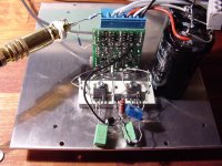
However a few pictures are no problems, first the birdsnest of the small 50W N-channel amplifier. It uses two IRF640N devices, but even smaller ones will do fine. You can almost see how i have made the output circuit in this picture, if you look closely. The green PCB in the back is a small folded cascode voltage amplifier, and power plug, to unplug everything in case of problems, when experimenting. 🙂 The voltage amplifier also features soft clipping and a total rail loss with N-ch devices of around 4 V (similar to a bipolar output device with 0.22 Ohms emitter resistors).
Just by replacing the IRF640N's to something bigger you can increase outut power to much higher levels. The rest of the circuit is calculated for +/-100 Volts supply, and 5nF capacitive load, so around 500 Watts in 8 Ohms should be no problem.
Attachments
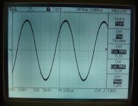
Below you can see the output waveform. Note the frequency, 100 kHz is the highest this sinewave generator will go. But the amplitude is not even 1dB down compared to 1 kHz.
If you notice a small ripple on the top of the sine wave, it is due to the feedback being shifted to before the output circuit over 50 kHz. This is to maintain stability in high capacitive loads, without sacrificing bandwidth. See the ULCA thread for further details on that one.
Output power here is just 16W (the transformer is a 30VA, and it's sweating!) 😀
- Home
- Amplifiers
- Solid State
- N-Channel mosfet amplifier schematic needed