What matters (to me) is distortion over the audio band, whatever the amount of NFB.
Using the same active components, I, at least, cannot design am amplifier with 40dB more NFB (or lower bandwidth, if you like) but with the same linearity.
My experience is that you always have to sacrifice linearity for open loop gain.
So using OLG bandwidth alone as argument is, for me, misleading.
Of course there are other arguments for feedback, such as Zout for power amps.
Cheers,
Patrick
DIY is a hobby, sure. But electrical engineering doesn't have ' alternative facts' ;-)But DIY is about free choice, not universal truth, not ?
Cheers,
Patrick
Jan

But electrical engineering doesn't have ' alternative facts' ;-)
Then just use OPA1656, etc. for everything.
Or better still, use composite opamps to get -140dB for everything.
Why bother with DIY.
Patrick
Last edited:
There's several variables that make a clean comparison not simple.Let's say I have 2 amplifiers with the same closed loop gain and distortion at 1kHz.
Amplifier 1 has an open loop bandwidth of 10Hz.
Amplifier 2 has an open loop bandwidth of 20kHz.
But assuming they both have the same OL gain at 1kHz, what seems clear is that amp 1 has (much) lower distortion below 1kHz than amp 2.
Which one you prefer to listen to is a personal preference.
I understand the intuitive preference for something that looks like a flat line on a graph.
But electrical engineering isn't about intuitive preferences.
Intuition is a shortcut to a quick decision with minimal thinking but it can come around and bite you in the rear end!
Jan
Only you can answer that for you, Patrick.Why bother with DIY.
Patrick
I'm not going to tell you why you should have or not have a particular hobby!
Jan
I understand the intuitive preference for something that looks like a flat line on a graph.
It is not about a flat line for OLG, Jan.
It is about a flat line for distortion over the frequency range.
If you can achieve that with a 10Hz open loop bandwidth, I am all for it.
But that means the circuit has decreasing distortion with increasing frequency in open loop.
I rather think the opposite is true.
Patrick
Good idea!Then just use OPA1656, etc. for everything...
I was looking for alternative opamps for DC servo; these go straight to my shopping list.
Rest assured I'll not use them "for everything" 🙂
When confronted with several options, "use your intuition" (John Curl).There's several variables that make a clean comparison not simple.
But assuming they both have the same OL gain at 1kHz, what seems clear is that amp 1 has (much) lower distortion below 1kHz than amp 2.
Which one you prefer to listen to is a personal preference.
I understand the intuitive preference for something that looks like a flat line on a graph.
But electrical engineering isn't about intuitive preferences.
Intuition is a shortcut to a quick decision with minimal thinking but it can come around and bite you in the rear end!
Jan
Audio is way beyond vanilla engineering, and picking the right preference is what makes a great solution instead of an OK-ish solution.
Hmm, just good for a DC servo ….. the Big Guys have planted a lot of bad seed into the DIY audience.I was looking for alternative opamps for DC servo; these go straight to my shopping list.
Good for measurement equipment, like the Autoranger.
All thanks to you and Jan :
https://www.diyaudio.com/community/threads/autoranger-for-soundcards.299635/post-7474015
https://www.diyaudio.com/community/threads/autoranger-for-soundcards.299635/post-7529011

Patrick
All thanks to you and Jan :
https://www.diyaudio.com/community/threads/autoranger-for-soundcards.299635/post-7474015
https://www.diyaudio.com/community/threads/autoranger-for-soundcards.299635/post-7529011
Patrick
You have one single proof that it is not good for a link level stage? Do you ever do controlled double blinded tests, or stick with sighted tests like most audiophiles do? Belief or proof?
It should be pointed out at this stage that although TPC/TMC shows a wider loop gain bandwidth, it is not contradictory with what Jan is saying. The reason for this is when you use Miller comp with a single, low frequency dominant pole aka pole splitting, you force the amp slope to 20 dB/decade from a low frequency and set the phase shift between the LF pole and the ULGF to 90 degrees max.
If you examine the amplifier open loop response before any compensation you will see that the first pole, formed usually by the VAS/TIS stage, is a few kHz and in some topologies 10s of kHz. What TPC/TMC does is exploit this by placing the ULGF as per normal (1-3 MHz as already discussed and dependent upon the OPS configuration) and then the slope downwards in frequency is set at 20 dB/decade so the amp is stable, then at some frequency at around 500 kHz, you increase the slope to 40 dB/decade. The net result is the 40 dB/decade scope intersects the amplifier open loop gain at the aforementioned few kHz or 10s of kHz depending upon amplifier specifics. You get worthwhile reductions in distortion at the top end of the audio band, something you can verify with a two tone 19+20 kHz IMD test. TMC/TPC usually doesn’t show any distortion improvement at LF over Miller comp in a power amp (caveat: these are my test results on a few different CFA designs - VFA may well be different, I have not looked into it). Typically, you should see a 6-10 dB improvement. This of course arises because the loop gain at 20 kHz is no longer circa 35 dB, but about 60 dB. Please note, I am talking about audio power amps here. For modern opamps with their greater GBWP, you do indeed get very high loop gains at 20 kHz in any event because the OLGs at 10 Hz are 130-140 dB.
YMMV 🙂
Slightly OT: did you implement something to protect the inputs of the COSMOS ADC? Some sacrificial resistors?Good for measurement equipment, like the Autoranger...
No. Did not use an input limiter, if that is what you mean.
It's input has resistor attenuator.
Adding external resistor will change the gain, I think.
Patrick
It's input has resistor attenuator.
Adding external resistor will change the gain, I think.
Patrick
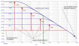
Although I mostly knew what Jan was talking about in his dialog (respecting amplifiers of narrow band and wide band nature), it wasn't absolutely clear that the narrow band began at zero frequency. In other words it was questioned if Jan could be talking about an amplifier being of narrow band in being subjected to a high pass filter.Example of different open loop gain plots with same GBW = 55MHz (gain bandwidth product, see the crossing with 0dB). That's what Jan is showing.
The discussion may be on overload recovery in individual cases, which is to be solved properly.
View attachment 1249342
This leads to a thought that it might be an improvement to his presentation to create and refer to a Figure as per the attachment above, but perhaps with just two lines showing two open loop amplifiers.
To go further the diagram could include a downward facing arrow from the top trace to the bottom trace, indicating the inclusion of feedback to the extent matching up to the open loop amplifier, and then compare the results of a closed loop amplifier having the same frequency response to one having no feedback. It seems that this is mostly at the root of the discussion intended to support variant considerations.
Okay.To go further the diagram could include a downward facing arrow
There are formidable devices out there...the OPA1656 being one. And the thought does cross my mind as to "why bother".Then just use OPA1656, etc. for everything.
Or better still, use composite opamps to get -140dB for everything.
Why bother with DIY.
If someones intention is to simply copy in order to save money than DIY seems a highly questionable engagement. However if the intention is to beat the (...include worthy expletives here...) OPA1656's on their specifications (seemingly highly difficult), or don't believe that their documented specs are entirely relatable to sonics, then beginning by understanding the basics of distortion seems well within the boundaries of DIY, particularly for a newbie (someone that could "rise like a phoenix from the ashes of his pathetic life" and create the next great opamp).
Interestingly I am currently engaged in using composite pampas (note - "pampas". is the autocorrection that this site uses to replace "opamps", it is an noun that means "extensive, treeless plains in South America"). My composite pampas network is made up of an input low bandwidth opamp and an output wide bandwidth device set for unity gain bandwidth.
Last edited:
Not quite what I had in mind in relation to what seems of core intent by Jan PMA... It depends on the audience that Jan is interested to enlighten.
My idea was rather leave only two lines, one blue line at perhaps the 40dB line, as shown in your figure and the other at perhaps 80dB. These being identified as two independent amplifiers, whereupon the upper amplifier contains a downward line starting from 80dB and ending on the 40dB line, being indicative of 40dB of feedback correction, such that the frequency response and overall gains match for both. Hence the comparison is between a 40dB open loop amplifying device for example, and that of an 80dB open loop amplifying device with 40dB of feedback.
It seems that basic forms of distortion analysis begins from a comparison between amplifiers with feedback and those without and go from there. Once again I don't know if that is what Jan intended.
My point was the intuitive preference for flat graphs, period.It is not about a flat line for OLG, Jan.
It is about a flat line for distortion over the frequency range.
Patrick
Except for investments, of course ;-)
Jan
For audio power amp some designers will chose circuit with about 70dB OLG flat from DC up to 20Khz with less as posible OL distortion , further adding negative feedback factor of about 50dB to get an audio amp with about standard 20dB of CLG , IMHO 50dB of loopgain ratio flat over full audio spectrum is also one very respectable number ,
I know that final THD numbers maybe will be not so stelar (0,000000...%) , but for one audio power amp will be just OK if not even more than that .
I know that final THD numbers maybe will be not so stelar (0,000000...%) , but for one audio power amp will be just OK if not even more than that .
Attachments
Last edited:
- Home
- Design & Build
- Electronic Design
- Myths, tricks and hey, that's neat!