Hi all-
Can someone possibly tell me what type of phase inverter this is? I've looked at all the types, long tailed pair, cathodyne, etc. but nothing looks similar.
This is on a PA amp that I'm converting to a guitar amp, so I'm planning on changing to a long tailed pair shortly.
I'd really like to know what this is though for my own education.
Any help would be appreciated.
Thanks!
Glenn😕
Attachments
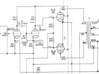
What you got there is a plain-vanilla split-load or concertina. Advantages are simplicty and the reliance on passive component tolerances to set balance. Disadvantages include strict requirements for load symmetry and less-than-unity gain, which transfers gain swing issues to the input stage.
Thanks for the information Sy.
Looks like I'll be going for the long tail pair PI sooner than expected.
Glenn😉
Looks like I'll be going for the long tail pair PI sooner than expected.
Glenn😉
porkchop61 said:Can someone possibly tell me what type of phase inverter this is?
porkchop61 said:
cathodyne
This method is simple and it works. SInce you already have the amp and are converting it, why not leave it as it is and see what it sounds like, then convert it to another style later for comparison. Or if you like it, leave it.
Paraphase inverters are less suceptible to load variations. Here is some education on those 🙂
http://dogstar.dantimax.dk/tubestuf/paraph.htm
http://dogstar.dantimax.dk/tubestuf/paraph.htm
The other bad thing about cathodyne is it isn't good for much voltage, so you need an amplifier to drive stubborn tubes (like high voltage 6L6s needing 60V or more drive). This produces the Williamson driver circuit, but it has a lot of coupling caps so I don't like it. An LTP is a good way to get final drive requirements. I haven't done anything with paraphase but it seems like it has similar properties.
How 'bout that 6X8 paraphase? 😀
Tim
How 'bout that 6X8 paraphase? 😀
Tim
Sch3mat1c said:How 'bout that 6X8 paraphase? 😀
That one is just brilliant 😀
Fred had sent me a pile of them to me last fall.
Geek said:Fred had sent me a pile of them to me last fall.
I think i have a pile of those too...
dave
Heh, I think that's why Fred sent most of his stash to me. "Let's see what you can use them for", I believe were his words 😉
What could mean that numbers labelled with a triangle on the schemo ? AC peak or rms ?
32 at the driver anode and 3.6 at 6L6 grids ?
If dp missing, why 48 at 6L6 anodes ?
If square marked values are for DC, they are vy curious too !
Yves.
32 at the driver anode and 3.6 at 6L6 grids ?
If dp missing, why 48 at 6L6 anodes ?
If square marked values are for DC, they are vy curious too !
Yves.
Yvesm said:What could mean that numbers labelled with a triangle on the schemo ? AC peak or rms ?
32 at the driver anode and 3.6 at 6L6 grids ?
If dp missing, why 48 at 6L6 anodes ?
If square marked values are for DC, they are vy curious too !
Yves.
Those look like AC voltages, but referenced to a certain input which doesn't appear on that schematic fragment. The 48V at 6L6 anodes indicates that the stage gain is about 13. The DC voltages look pretty normal to me- what caught your eye as unusual?
SY said:
. . .
The DC voltages look pretty normal to me- what caught your eye as unusual?
If 1st half 12AX7 runs at 1mA (1 v accross 1K cathode res), then
there is 100v accross its plate res, and that calls for a 265v B+.
Right, since this is the 6L6 Vg2 too.
If so, how could the phase splitter have 280v on anode !
I just wanted to point that this schemo should be used with some caution.
Yves.
Yvesm said:What could mean that numbers labelled with a triangle on the schemo ? AC peak or rms ?
32 at the driver anode and 3.6 at 6L6 grids ?
If dp missing, why 48 at 6L6 anodes ?
If square marked values are for DC, they are vy curious too !
Yves.
Yes triangles are AC signal voltages measured with a VTVM.
Squares are DC measured with a 20kOhm/Volt meter no signal.
Is there something wrong with this schematic? I'm new at this tube stuff, so please pass on any wisdom you may have.
I can post the whole schematic if you like. Just let me know.
Thank you.
Glenn
Hi,
Please do.
As Yves pointed out there's something not quite correct with the voltages (DC) as shown.
Cheers,😉
I can post the whole schematic if you like. Just let me know.
Please do.
As Yves pointed out there's something not quite correct with the voltages (DC) as shown.
Cheers,😉
- Status
- Not open for further replies.
- Home
- Amplifiers
- Tubes / Valves
- Mystery (to me) phase inverter?