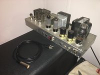
Hello, I've found this... "Amp" in a room of a house that I recently purchased, and I do have a pretty good handle on electronics, myself. I was thinking that I could get it in order. The thing is, it has no manufacturer's name, but it looks like a clone of an early Marshall. The power cable is... An XLR Microphone cable?
I actually have an old Sencore tube tester, and all of the tubes test fine. It's draws about 80 watts at the wall, with the power switch on, on standby. Turn the standby switch to play though, and it instantly glows the power tubes bright blue and screems extremely loudly, no matter if there is an instrument plugged in or not, or the positions of any knobs. If you strum the guitar plunged into it, with the knobs at 50%, you get a quarter of a second of beautiful tone, and screech. Also, draws over 2 amps at least.
So... Any ideas? 2 12ax7 and one 12au7 in the preamp, 2 MESA el-34 power tubes.
Attachments

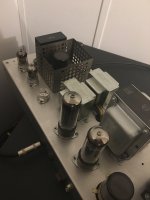
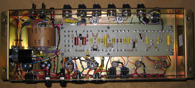
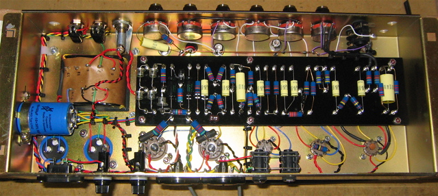
Not enough pics to really see what is what, but the unit looks handmade. There are also lots of wires under the perfboard that obviously connect to hidden points on the other side.
For a quick check, you can pull the phase inverter (12AU7) and see what the thing does. This would separate the power tube circuitry from the preamp tubes. My guess is that the unit will probably still be unstable with the 12AU7 removed, indicating a bias or feedback problem with the output stage. Naturally, I wouldn't trust anything to work as it should. Pinning the tail on the donkey is much easier when you aren't blindfolded, and at this point, we are.
P.S. : This thread might be better off in the Instruments & Amps forum.
Last edited:
...For a quick check, you can pull the phase inverter (12AU7) and see what the thing does. This would separate the power tube circuitry from the preamp tubes...
I just removed the 12au7 tube, and the scream is gone. But, so is any sound. Also, still draws a lot of power and the power tubes get super bright blue with a low electrical humming sound. So... The power side might be okay? Also, there is a small pot on that board, maybe should I try to adjust it, might set the bias?
Attachments
No don;t adjust it just to see what happens.
Pull the power tubes and power it up, is the excess current draw from the mains much reduced now? Obviously no sound will happen. In any case, now measure voltage at the power tube sockets. Is there reasonable bias at pin 5 of each socket? reasonable being maybe -45v more or less. Also is there B+ on both pins 3 and 4 of each, I assume there is because it amplifies, but check. And with power off, check resistance to ground from pins 1 and 8 of each socket. Should read zero ohms or maybe 1 ohm if they added sense resistors.
If the bias is gone or way off, fix that before installing the tubes again.
If the tubes can be biased, we can power up with the tubes. When you tell us the thing screams regardless of anything you do, and we see it is home made, my first suspicion is the plate leads on the output transformer are reversed. The left power tube has the right one's wire and the right one has the left's. If reversing them stops the howl, I was right. ANother way to test that is to find the negative feedback line - NFB - and disconnect it from the output of the amp.
Looking at the photo, the little control lying near the top end of the perf board is clearly a bias adjust. We can see the rectifier and little filter caps associated with it. With no power tubes in, you can adjust it to see if the pin 5 voltage changes. Set it to about -45v as a good starting point, then you can tweak it later.
Also measure the ripple on the bias supply. It ought to be very low. If there is a ton of ripple, and likely voltage about half what it ought to be, then you likely have lost the filter cap in teh bias supply.
Yes, this thread belongs in the instrument amp section.

Its mono right? Could you try to draw a schematic? If its mono, then it likely has reverb circuit, maybe like fender. Here is an idea of what part of it might be:
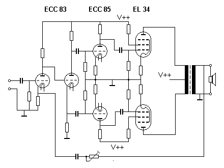
Looks to have two OPT's though - might be two separate single ended, with primaries tied together on one end to make push-pull? I might be way off on this though.
It does seem likely that the pot on the bottom of the board sets the bias. But if its based on the above circuit the pot is likely for the global feedback loop.
One of the 12ax7's could be for the reverb. That would make sense to me. Maybe it needs input - like a pedal, then it will simply work? 😉
Ian
Last edited:
I don't think those are output transformers. Look at post #2 photo. The near end is the power transformer, next is the output transformer. I might believe they are chokes, and someone built this thing with way more power supply filtration than it needs.
The small transformer at the far end is problematical. I guess it could be a reverb, but I see no jacks for the reverb pan connections. And with only three small tubes, one being the phase inverter, I am not sure there are enough tubes in it to support a reverb. Maybe.
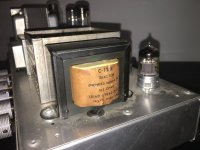
I remain convinced the small pot is bias adjust, simply because I can see it is wired to a small negative supply circuit.
The small transformer at the far end is problematical. I guess it could be a reverb, but I see no jacks for the reverb pan connections. And with only three small tubes, one being the phase inverter, I am not sure there are enough tubes in it to support a reverb. Maybe.
I remain convinced the small pot is bias adjust, simply because I can see it is wired to a small negative supply circuit.
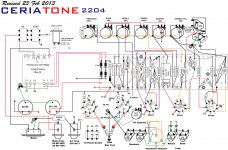
Here is a pretty equivalent drawing for easier reference:
Still haven't seen the gut shots of the power tubes, output transformer or power transformer sections. It doesn't look like a load was connected while the pics were being taken. Please tell me you didn't run it without a load connected. I would be very suspicious that this may have occurred sometime in the past by a previous owner.
Still haven't seen the gut shots of the power tubes, output transformer or power transformer sections. It doesn't look like a load was connected while the pics were being taken. Please tell me you didn't run it without a load connected. I would be very suspicious that this may have occurred sometime in the past by a previous owner.
Two extra 6v transformers? This really was an amateur build then.
Ralph, that is not really a schematic, that is a layout drawing. But we get the point.
A schematic shows the electrical relationship of the parts in the circuit. A layout shows the mechanical relationship of the parts in the circuit.
Ralph, that is not really a schematic, that is a layout drawing. But we get the point.
A schematic shows the electrical relationship of the parts in the circuit. A layout shows the mechanical relationship of the parts in the circuit.
I did have a load connected any time there is power going to it, it's just that the 4 ohm cabinet has a very short speaker cable, and had to disconnect it to look under it.
Do you think that it's okay that it has those green Mylar caps, almost every build I've seen uses yellow wrapped glass capacitors.
Here is a short and loud video of me flipping the standby switch so you understand the noise it makes. Watch for the blue in the power tubes, too.
http://youtu.be/92kHjXDf2Uo
Attachments

Well, after watching the video, I can tell you a few things:
1. This unit is doing its best to work. Loosely following the layout, it may be 99% correct in a connect-the-dots sort of way.
2. The unit is self-oscillating.
3. The thing sounds pretty loud.
This amp looks to be made of decent enough parts to not need much as far as parts to make good loud sounds. The chassis looks OK. The tubes look OK, and have been tested to work. The perfboard is what it is. Could be better, but should function if everything is connected properly. The money got spent on all the expensive stuff already.
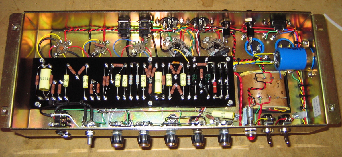
The major problem with this unit is the atrocious wiring. Maybe this thing has been through a microscope or two in a connect-the-dots manner a couple times, maybe the builder gave up trying to get the gremlins out before something let out smoke. Either way, there are a ton of wiring mistakes inside the shell. All of the curly-q wires weaving their way in and out of each other between what they connect act as antennas, transmitting signals willy-nilly in the signal path. This works just like having microphones next to speakers. Tidying up the wiring, keeping them short and straight as possible between connection points will help profoundly. Separating primary transformer wiring from secondary wiring, power from signal, input from output, and send from return wiring will need to be done. Why the builder didn't follow the layout diagram you posted is beyond me, but the wire dress on that diagram looks a WHOLE lot better than the finished product. It sure would have increased the odds of success without the symptoms you have now.
Here are a few examples of decent lead dressing:
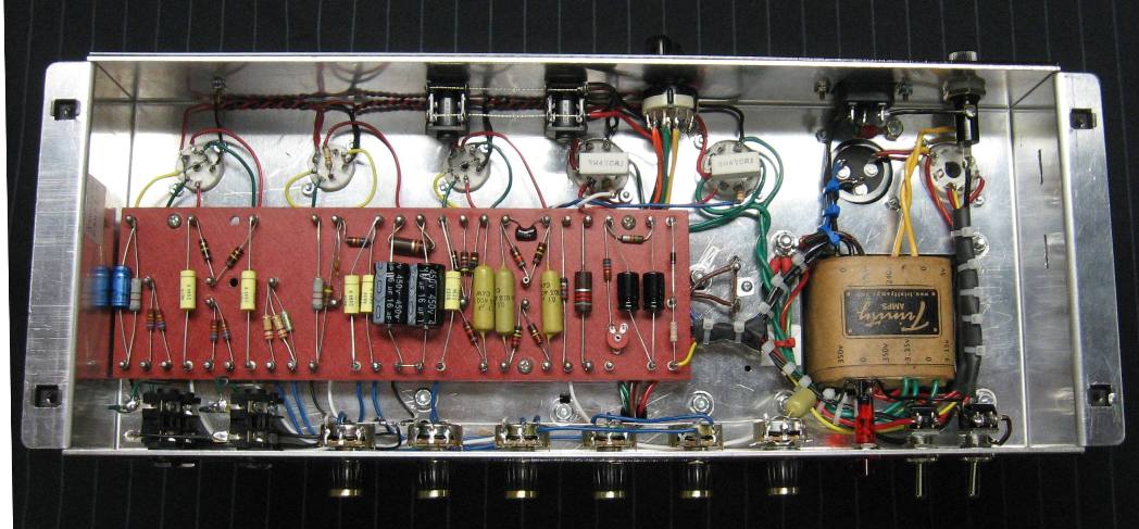
Besides eliminating situations like the oscillation you are hearing, keeping the heater wires away from the signal path wires cuts down on hum, keeping signal wiring cuts down on crosstalk and hiss, etc. It also makes the unit much easier to "read" as to what connects to where, reducing the need to trace the circuit on a schematic. If something goes wrong in the future, troubleshooting and changing components becomes much less trouble. Plus, it just plain looks more expensive.
There are more things I see wrong in that last gut shot, such as: Why did the builder not use the heater windings on the power transformer? Those Hammond PT's are pretty stout for this layout. No real need for extra iron. And what do the extra switches and such not do any more? Ground lift that never got connected? Hmmmm....
I hope you're good at twisting and soldering wires. Good luck.
1. This unit is doing its best to work. Loosely following the layout, it may be 99% correct in a connect-the-dots sort of way.
2. The unit is self-oscillating.
3. The thing sounds pretty loud.
This amp looks to be made of decent enough parts to not need much as far as parts to make good loud sounds. The chassis looks OK. The tubes look OK, and have been tested to work. The perfboard is what it is. Could be better, but should function if everything is connected properly. The money got spent on all the expensive stuff already.
The major problem with this unit is the atrocious wiring. Maybe this thing has been through a microscope or two in a connect-the-dots manner a couple times, maybe the builder gave up trying to get the gremlins out before something let out smoke. Either way, there are a ton of wiring mistakes inside the shell. All of the curly-q wires weaving their way in and out of each other between what they connect act as antennas, transmitting signals willy-nilly in the signal path. This works just like having microphones next to speakers. Tidying up the wiring, keeping them short and straight as possible between connection points will help profoundly. Separating primary transformer wiring from secondary wiring, power from signal, input from output, and send from return wiring will need to be done. Why the builder didn't follow the layout diagram you posted is beyond me, but the wire dress on that diagram looks a WHOLE lot better than the finished product. It sure would have increased the odds of success without the symptoms you have now.
Here are a few examples of decent lead dressing:
An externally hosted image should be here but it was not working when we last tested it.
Besides eliminating situations like the oscillation you are hearing, keeping the heater wires away from the signal path wires cuts down on hum, keeping signal wiring cuts down on crosstalk and hiss, etc. It also makes the unit much easier to "read" as to what connects to where, reducing the need to trace the circuit on a schematic. If something goes wrong in the future, troubleshooting and changing components becomes much less trouble. Plus, it just plain looks more expensive.
There are more things I see wrong in that last gut shot, such as: Why did the builder not use the heater windings on the power transformer? Those Hammond PT's are pretty stout for this layout. No real need for extra iron. And what do the extra switches and such not do any more? Ground lift that never got connected? Hmmmm....
I hope you're good at twisting and soldering wires. Good luck.
Last edited:
Disconnect the feedback wire. This is the wire on the speaker impedance selector switch which doesn't go to the output transformer or ground. In fact, it's probably the only wire that goes from the speaker selector switch to the circuit board.
Once this wire is disconnected, if the amp stops squealing then the 2 wires from the output transformer primary to the output tubes need to be switched around.
Get rid of that XLR connector on the power cord! Using a connector for something that it's not intended for is bad news.
Once this wire is disconnected, if the amp stops squealing then the 2 wires from the output transformer primary to the output tubes need to be switched around.
Get rid of that XLR connector on the power cord! Using a connector for something that it's not intended for is bad news.
Last edited:
Disconnect the feedback wire. This is the wire on the speaker impedance selector switch which doesn't go to the output transformer or ground. In fact, it's probably the only wire that goes from the speaker selector switch to the circuit board.
Once this wire is disconnected, if the amp stops squealing then the 2 wires from the output transformer primary to the output tubes need to be switched around.
Get rid of that XLR connector on the power cord! Using a connector for something that it's not intended for is bad news.
You are referring to the wire marked "x" on the layout diagram, going from the circuit board to the 4 ohm on the output selector?
I don't see a wire marked "X" anywhere but I'm pretty blind... But that sounds like the wire.
When you disconnect that wire and the squealing stops, you have the output transformer out of phase, so instead of it being "negative feedback" that tap becomes "positive feedback" to the amplifier. This will make an amplifier oscillate.
If this is the case, To fix this, locate pin 3 on the output tube sockets and switch the wire from pin 3 of one socket to pin 3 of the other socket and vice versa.
Last edited:
- Status
- Not open for further replies.
- Home
- Live Sound
- Instruments and Amps
- Mysterious (haunted?) screeching amp, Marshall, maybe?