Thank you ALL very much for your kind help... I will explore in detail at the upcoming weekend.
Have a wonderful week ahead 🙂
Have a wonderful week ahead 🙂
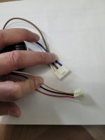
If I may, I would like your opinion on the wires of Talema transformer...
The primary is BLUE / BROWN/ WHITE. If I understand correctly BROWN is 115V, BLUE is 115V and WHITE is 0V.
The secondary is ORANGE / BLACK / RED. Again, I believe RED is +ve V, ORANGE is -ve V and BLACK is 0V
Thank you in advance
The primary is BLUE / BROWN/ WHITE. If I understand correctly BROWN is 115V, BLUE is 115V and WHITE is 0V.
The secondary is ORANGE / BLACK / RED. Again, I believe RED is +ve V, ORANGE is -ve V and BLACK is 0V
Thank you in advance
Attachments

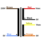
I believe you’re almost correct. Both primary and secondary are arranged as series-connected windings, and the brown and black leads are more properly termed center-taps. Applied in circuit, the black wire will be at earth/ground and the red and orange wires will show roughly 20 VRMS re ground with opposite phases. The wiring in the primary is less certain, but I believe mains connected primary will be drive with about 230V between the white and blue leads, and the brown lead will measure about 115V with respect to the mains “neutral“.
Resistance measurements should confirm equal resistance between the center-taps and either end of the windings and verify that the black and brown leads are winding center-taps.
Resistance measurements should confirm equal resistance between the center-taps and either end of the windings and verify that the black and brown leads are winding center-taps.
Thank you... the resistance measurements on secondary confirmed my understanding. Because of the fault on the primary side, no measurement was possible... however 230V across the BLUE and WHITE should be correct in theory.
Thanks again
Thanks again
Normally the primary winding wouldn't be center tapped. It's usually a single winding for fixed voltage or two windings for 120/240 operation. The extra wire may connect to a screen. Can you verify how it was connected?
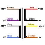
Exactly.... I didn't expect 3-wires primary!! I will have to clarify this at the weekend once I pulled the unit completely apart. My gut feeling is that because Myryad designed their products for both 115-120V & 230-240V markets and thus there should be 0V / 115-120V / 230-240V lines and based on the voltage selection, different AC line is used to operate the unit.
The "unlike" part for me here is, based on the Australian standard 240VAC, brown is active; blue is neutral and green/yellow is earth... ie messing the brown and blue lines in equipment a very bad practice 🙁
Thank you all for your insights 🙂
The "unlike" part for me here is, based on the Australian standard 240VAC, brown is active; blue is neutral and green/yellow is earth... ie messing the brown and blue lines in equipment a very bad practice 🙁
Thank you all for your insights 🙂
- Home
- Amplifiers
- Solid State
- Myryad MXP2000