(...)
>100dB speakers will require a very low noise value at the amplifier output.
Chipamps do not have that required very low noise value. Peter Daniel developed his implementation that he uses (or used) with 95/96dB/W@1m speaker, I cannot recall if he had reservations on noise.
Agree completely!!, 2myrefC builds v1.2 and v1.3 boards, the hiss is always there, PGDN floating helps. but not that much, better to use less sensitive speakers, myref diserves it IMO
No. Soft start is for current limiting when the mains transformer is asked to start up. We already need/use that for the close rated mains fuse that we should all be using.Andrew, is this a situation where a discrete soft start module would help?
Here (noises in the speaker) we need fast OFF for the relay driver circuit. We already have slow ON.
Understood - the soft start would work if the amp was up side down or I was standing on my head.😀
Ok, I still can't get one of my amps to work, and I have no idea why.
I've replaced the capacitors in the LM318 section, I've replaced the LM318 (I tried two different LM318's), and I've replaced R14 with a 100R resistor, and I still can't get the relay to click on, the power LED to light, or music to play.
I've been through every component and everything is connected properly, orientated properly, and soldered properly.
I'm running a soft start circuit sold by Per-Anders Sjostrom, however that fires up one of the channels, and I've used it on another chip amp project with no problem.
Can someone please help me before I take a sledge hammer to it.
Thanks
Ok, I still can't get one of my amps to work, and I have no idea why.
If rails are good, you checked all parts and they seem the right ones in the right place with the right value, lm318 and LM3386 are good then a faulty board is possible but, IMHO, unlikely...
Can you post some pics?
I will post some pictures tomorrow, Clave.
I have calmed down a bit and reflected on the issue. I'm not entirely convinced that CPC Farnell sent me the correct PF capacitors - I had two Mica capacitors that had 22 printed on them, yet they were in seperate bags, with the part numbers relating to the correct capacitance (22, and 220).
What also makes me think that they sent the wrong capacitor, is the fact that the issue of the LED shining when the power is switched off, no longer happens.
I don't for one minute think it's the boards.
Thanks for the help.
For the speaker protection circuit, R21 reduced to 100k and R14 to 180R has given very dependable operation with both Omron and Goodsky relays, and a wide variety of transistors for Q1 to Q3.
For Rev C, C10 is 22p and C12 is 220p - measure them if there's any doubt.
Recheck the values of R5, R6, R8 and R9 to make sure they're sane. Compare with the working board.
Check for solder bridges/shorts from pads to the ground plane in the small-signal area.
For Rev C, C10 is 22p and C12 is 220p - measure them if there's any doubt.
Recheck the values of R5, R6, R8 and R9 to make sure they're sane. Compare with the working board.
Check for solder bridges/shorts from pads to the ground plane in the small-signal area.
Thanks Linuxguru, I will do that. R5, 6, 8, 9 *should* be the same as they are the parts that came with the kit, but you never know.
I didn't change R21, just R14, so I think I will keep that one in mind.
Attached are some pictures of the board - there are a few components on the underside, mainly due to the ease of fitting the oversized items. I haven't cleaned up the flux from when I was desoldering components, hence some of the gunge underneath.
Attachments


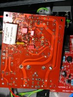
I would start from cleaning the flux...maybe it's not the problem... but I wold start from there...
Check for solder bridges/shorts from pads to the ground plane in the small-signal area.
Hi Linuxguru, what exactly is the small signal area that you mention in your post. Is it the LM318?
Thanks
...what exactly is the small signal area that you mention in your post. Is it the LM318?
Yup, the area on the board that is shielded by the ground plane, including the input connector block, input cap, input filter, feedback network, compensation networks, Howland resistor networks, and LM318 opamp.
Some of these nodes have large voltage swings, so 'small signal' is a bit of a misnomer.
Still no joy - I've swapped R14 and R21 for the values discussed, checked for solder bridges using a magnifying glass (none found), and double checked all the capacitors. The board refuses to work.
westers151
I would verify the build instructions against what you've already placed. From reading in this thread, the percentage of builders who misplaced or left out components is more than four times those that claim a defect and many of those who discovered their error initially suspected defect so that ratio may climb even higher.
I would verify the build instructions against what you've already placed. From reading in this thread, the percentage of builders who misplaced or left out components is more than four times those that claim a defect and many of those who discovered their error initially suspected defect so that ratio may climb even higher.
I'm not claiming a defect (I have one channel working and it sounds fine), I just don't understand why this one isn't working.
I did follow the build instructions to the letter, however I have gone back (yet again) to verify all the components, and they are fine. However, as a result of doing that, the board is now broken; I had to lift some resistors to double check the values, and as a result of doing that I have lifted the pads on one of them.
Linux Guru - Do you have any of your boards for sale? I don't fancy doing the surface based soldering on Clave's (although I may have to if there are no through hole boards left).
Find your bad pad. Find the trace associated with it. Scrape the soldermask off of the trace. Solder onto the scratch instead of the pad.
There is no trace on the one with the lifted pad - it's R14, and the leg that isn't connected to a trace.
Also I have started doing surface mount soldering and I find it very easy. Yes a magnifying glass is helpful. Just tin one pad then grab part with Tweezers and touch part to tinned pad while touching both with the iron. Use a lot of flux on parts with more than two legs to avoid solder whiskers between two legs. With through hole we have to bend leads, place component, bend again, flip board, trim. SMT is just tin pad, hold in place, heat, solder other side. Not bad.
Maybe the trace is on the other side of the PCB.
The resistor must have a purpose and for that it must be connected at both ends to the circuit.
The resistor must have a purpose and for that it must be connected at both ends to the circuit.
Yes, it's on the top of the board under R23, but hidden by R23 when that is installed.
However, what is more interesting is the behaviour of my soft start when the "faulty" board is not connected to the power.
When the "faulty" board was connected to the power, I could see the operation of the two relays in the soft start circuit. What I noticed was the delay relay didn't pull open all the way - it only moved a little, but obviously enough to power on one of the boards.
With the "faulty" board removed from the power, the delay relay in the soft start now opens fully, and with a much louder click.
However, power is getting through to the "faulty" board (when I connect it all back up), as I've measured the correct rail voltage for both V+ and V-, as well as the 12V for the LM318.
- Status
- Not open for further replies.
- Home
- Amplifiers
- Chip Amps
- MyRefC build guide