I recall Mauro provided a good list on layout practices, as usual the devil is in the details.
Yes, I've read it.
And I'm reading other interesting documents too.
Not too long ago working on a different design, I discovered that any two components placed close together will interact with each other, due to the electromagnetic effect of the small amounts of current. So it's also a good practice to check the direction so that these sort of run perpendicular to each other.
Can you elaborate, please?
Thanks 🙂
I'll try to explain using the example of two wires, if you have two wires running in parallel, but the currents are running in opposite directions, then each conductor will be under the influence of the magnetic field generated from current running in the other conductor, to minimize this effect, you can have the traces jump over each other, or if the traces are further away from each other, the influences are minimized. If they have to be close together and in parallel, currents running in the same direction is much better than in opposite directions. When it comes to components, if you have caps or resistors jumping over traces, then the currents are most likely to be running perpendicular to each other, but do take note of how the cap and resistor structure might change the current/magnetic field direction.
Oh, also keep the higher current sections away from the inputs of lower current sections. Someone did a mistake here in one of my amps, and the results were sound more dead and compressed accompanied with higher distortion measurements.
Oh, also keep the higher current sections away from the inputs of lower current sections. Someone did a mistake here in one of my amps, and the results were sound more dead and compressed accompanied with higher distortion measurements.
Last edited:
D3 doesn't work !
Downside of using 2 bridges.
Hi Rudy,
do you mean that D3 should be connected to NAC1, right?
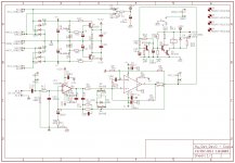
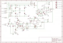
Take a look on the updated schematic, now it should work...
Thanks 🙂
PS
Soongsc, is it any better now?
Attachments
Last edited:
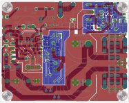
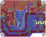
Is this a double sided board? What do the blue and different shades of red represent?
Yes, Soongsc, it's a doule sided board.
Red is the component side, blue the solder side.
Red is transparent so the darker red represents a trace in the bottom layer.
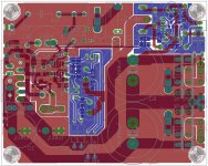
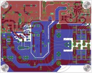
In the meanwhile I've updated the PCB
Attachments
Last edited:
It's going to take a while to trace the schematic though the PCB.
Yes, it's not so easy... I've attached some pics to help.
Attachments
-
 RevO - Amp circuit.jpg212.5 KB · Views: 201
 -
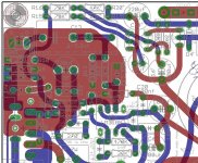
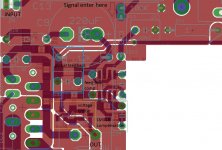 RevO - Amp circuit (detail).jpg235 KB · Views: 199
 -
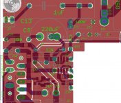
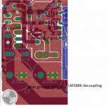 RevO - LM3886 Power supply decoupling.jpg187.1 KB · Views: 93
 -
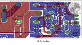 RevO - DC Protection.jpg245.3 KB · Views: 91
 -
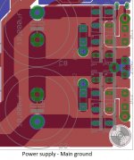 RevO - Power supply - Main ground.jpg174.6 KB · Views: 92
 -
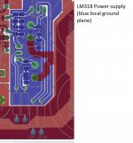 RevO - LM318 Power supply.jpg142.9 KB · Views: 102
The way you have the ground plane laid out is going to complicate things. Remember the old Rev C does not have a ground plane like that for a good reason. The circuits have less unaccounted capacitance in the signal path. I would only use this kind of ground for power voltage distribution. All the EMI shielding should be done using the chassis.
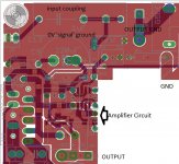
The amp output ground seems really close to the input ground. Not a good idea because that ground is still a high current point and it's going to effect the input. Unless you have done some analysis, and determine that is what you really want, generally, I would avoid it. It might be interesting to do some experiments though to see how if effects measurements and sound.
I'll continue to look through the amp section first, but those gray component markings really make it hard to read.
The way you have the ground plane laid out is going to complicate things. Remember the old Rev C does not have a ground plane like that for a good reason. The circuits have less unaccounted capacitance in the signal path. I would only use this kind of ground for power voltage distribution. All the EMI shielding should be done using the chassis.
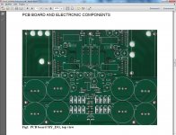
I've taken inspiration from the MY_EVO (Evolution) PCB, I've attached the only officially available pic (from the assembly manual).
Obiously it's possible that my version is wrong...😀
The amp output ground seems really close to the input ground. Not a good idea because that ground is still a high current point and it's going to effect the input. Unless you have done some analysis, and determine that is what you really want, generally, I would avoid it. It might be interesting to do some experiments though to see how if effects measurements and sound.
Yes but the TP RevC PCB is not much different in that regard...only 2 cm more distant.
I'll try to gain distance.
Maybe I can avoid the overlap of the 0V plane (signal ground) with OGND trace, it can help?
I'll continue to look through the amp section first, but those gray component markings really make it hard to read.
I've attached a new version of the amp detail with green component marking, I hope it will help you.
I appreciate very much your comments and your help, Soongsc, thanks! 🙂
Attachments
Last edited:
I'm looking at the old Rev C and wondering how the output ground is connected. Is it an interchannel connection? The RevO output ground, almost looks like it's connected to 0V ground, I may be reading it wrong. But the location seems too close to the input components.
I wonder how the Evolution listening impressions are compared to Rev C with the new layout.
I wonder how the Evolution listening impressions are compared to Rev C with the new layout.
I'm looking at the old Rev C and wondering how the output ground is connected. Is it an interchannel connection?
The output ground is connected by the relay to starground
The RevO output ground, almost looks like it's connected to 0V ground, I may be reading it wrong. But the location seems too close to the input components.
No, like the RevC the output ground is connected by the relay to starground.
In the My_Evo Mauro choose a more traditional approach and the output is controlled by the relay, output ground is directly connected to the star ground.
I wonder how the Evolution listening impressions are compared to Rev C with the new layout.
I hope very similar... but first we should have the new PCB... 😉
In the meanwhile, inspired by your suggestions I'm trying to get a better grounding...
I'll post soon the updated PCB.
I discovered the relay after I typed the question. Is the turn on/off thump really bad without the relay?
I discovered the relay after I typed the question. Is the turn on/off thump really bad without the relay?
Never tried without... but Mauro said that in the first seconds the amp must stabilize and make noise, if I remember correctly...
Last edited:
This looks like an exciting layout. You are so fast I have trouble keeping up.
One thing I wonder is that if the power traces are on the opposite side of the power ground, if the traces are wide, then there will be more capacitance, will this improve power supply high frequency performance?
One thing I wonder is that if the power traces are on the opposite side of the power ground, if the traces are wide, then there will be more capacitance, will this improve power supply high frequency performance?
This looks like an exciting layout. You are so fast I have trouble keeping up.
😀
Thanks Soongsc.
Since in these days I'm at home from work I'm dedicanting much of the day to this project.
One thing I wonder is that if the power traces are on the opposite side of the power ground, if the traces are wide, then there will be more capacitance, will this improve power supply high frequency performance?
Sadly I don't have a solid technical background so while I find and read documents on PCB design I try to apply what I learn.
If I've understood correctly, the return current, if a ground plane is available, tends to follows, in the opposite direction, the same path of the supply/signal tracks.
So the ground plane can follow the same path of the supply tracks and being wider at the same time it gives some shielding.
In addition added capacitance seems to be benificial as lower impedance.
The only thing I can say for sure is that this sort of power supply routing is not new, the My_EVO use the same concept and also the QRP02 of Peranders uses a similar routing.
Mmmh, this thread is more like a blog... 😀
I've revised both PCB and schematic.
Until a find a suitable (and simple) power supply which sounds better than plain zeners I'll keep the latters in schematic.
I've modified grounding:
I've revised both PCB and schematic.
Until a find a suitable (and simple) power supply which sounds better than plain zeners I'll keep the latters in schematic.
I've modified grounding:
- now the 0V signal reference is linked to the LM318 PS ground plane to optimize return currents
- the LM318, his compensation network and input and output traces are no more on the 0V groundplane
- Incresed distance from adiacents planes on the same side to reduce stary capacitance.
Attachments
Last edited:
Dario, The power supply change appears to be a major shift from the path you were on. I'm not clear on what you mean by " power supply which sounds better". Can you explain? Do you mean sounds more logical from a PCB layout point of view - or effects the sound of the amp in a more positive way?
Last edited:
Dario, The power supply change appears to be a major shift from the path you were on. I'm not clear on what you mean by " power supply which sounds better". Can you explain? Do you mean sounds more logical or effects the sound in a more positive way?
In the last days I've tried some alternatives PS and none sounded better than the plain zener one...
So, until I find a simple circuit that sounds better, the PCB evaluation and refinement phase will proceed with the original PS but with higher voltage.
But at the end you can be sure the LM318 PS will be different and better. 😉
- Status
- Not open for further replies.
- Home
- Amplifiers
- Chip Amps
- My_Ref RevO