Dario, interesting those Mresist.
The Isabellenhutte are the same package (TO247).
I use them in your board, one needs to adapt the pins.
Not a big problem, space is there.
Security Check
Ciao, George
George,
Can you speak more on how you adapted the pins? The 1.5 mm width would seem to be as big a problem as the 10 mm lead spacing. The Mresist actually look easier to adapt because they have on leads, but it is still a challenge.
I think you may be right about the source.
Jac
I have bent 90deg the original pins, perpendicular to the resistor body plain. (close to the body)
Then soldered a nice copper leg to the originals, like 0,8mm ideally. (L shape also this)
This then can be soldered in the original pinout.
Ciao, George
Then soldered a nice copper leg to the originals, like 0,8mm ideally. (L shape also this)
This then can be soldered in the original pinout.
Ciao, George
Company specialized..? I would say softly: Isabellenhutte.. 🙂 🙂
Package, dimensions, resistive material are the same.
Instead of copper, aluminium in the 'industrial' version.
I think they're a custom version of Powertron FPR2 (a german company too, part of Vishay).
Powertron FPR2-T218 30W Metal Foil Resistor | Hifi Collective
Look at the image from hificollective page:

I use them in your board, one needs to adapt the pins.
Not a big problem, space is there.
Sure, they can be adapted somewhat but for perfect and safe fit (I'm thinking about the heatsink) PCB must be partially re-designed.
If after trying them I will think they're worth the effort I'll redesign boards, I will probably ask you again to check the updated design. 😉
Dario,
You might be right. The datasheets of the Isabellenhutte, Powertron VPG, and Mundorf resistors all looks very much the same with a few differences.
On thing I am curious about is that hificollective says the Powertron uses bulk foil manganin and that is what VPG makes, but the datasheet just say CuNiMn foil, the same as the datasheets for the Isabellenhutte and Mundorf resistors. My guess is that all three are the same, but I don't know.
Jac
I have the same feeling, now I remember vaguely, but did not jump for the powertron for this very same reason: already have ~it implemented..
And yes, naturally, Dario!
Ciao, George
And yes, naturally, Dario!
Ciao, George
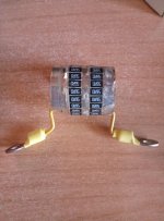
just to add a little bit of entropy about the sound of a power resistor in a (relatively) high current path I'd like to share my experience about an experimental power resistor that you can see in the photo, a 20 parallel 56 Ohm in series with another 20 parallel 56 Ohm thick film smd resistor to obtin a 20W (circa) 5,6 Ohm power resistor.
It was quite frustrating to hear at a ugly resonance in the mid-high region (Lowther are dramatic in this field), I was really disappointed with it. While dismounting them a couple of "pick" occurred with my nails on the composed resistor body (yes, I was quite rudest than the montage phase).
Well, the frequency mechanically generated by the resonance of my cylinder resistor was quite similar (if not the same) to the one I've heard during music reproduction...
So, the conclusion should be: no vibration on power resistor at all, better to be well dumped, but if a vibration is unavoidable, it should be generated by a well-sounding material. In my experience, based upon the sound of hard domed tweeters, aluminium is the worst, copper is quite good but titanium is absolutely the best (it tends more than any other metal to the soft dome sound while preserving the detail of a hard dome).
My personal experience, I repeat, but it might be interesting for someone, and maybe a suggestion for the heatsink (if any)?
Massimo
Attachments
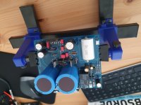
Almost three years ago I ordered the My-Ref Fremen PCB's. With the Corona lockdown I found some qualtiy time.
The soldering went well with 60/39. I think there is around 8 soldering joints, that did not flow easy at all. Don't know why.
Stil waiting for C10 (was missing in my order).
The soldering went well with 60/39. I think there is around 8 soldering joints, that did not flow easy at all. Don't know why.
Stil waiting for C10 (was missing in my order).
Attachments
Cowmans,
Glad you could get these boards going. One thought. If your 60/39 is typical resin flux solder, I recommend cleaning the boards with alcohol as soon as possible. Flux gets into places, like under IC chips, and can have enough conduction to cause problems. Of course, if you used "no-clean" solder, you are in a better place. I only mention it because I have messed up in the past.
Good luck
Jac
just to add a little bit of entropy about the sound of a power resistor in a (relatively) high current path I'd like to share my experience about an experimental power resistor that you can see in the photo, a 20 parallel 56 Ohm in series with another 20 parallel 56 Ohm thick film smd resistor to obtin a 20W (circa) 5,6 Ohm power resistor.
Massimo
Now that is an interesting experiment! In spite of the less than perfect results, I will bet it did a good job of cooling.
Jac
just for joke: maybe a 40ad 🙂)) series /parallel resistor on both faces like the quad, mounted in three stripes of solid copper (for solderability reason) insulated by mica or silicone between each others, or just with a few distance, letting the solidity of the structure be entrusted to the 40 resistances themselves resistors?
One thing that surely I don't like in the quad solution is the vetronite heated under the copper, I really don't like its smell...
a joke for sure...
One thing that surely I don't like in the quad solution is the vetronite heated under the copper, I really don't like its smell...
a joke for sure...
Almost three years ago I ordered the My-Ref Fremen PCB's. With the Corona lockdown I found some qualtiy time.
The soldering went well with 60/39. I think there is around 8 soldering joints, that did not flow easy at all. Don't know why.
Stil waiting for C10 (was missing in my order).
If You would go for revA style modification, then You do not need it. And you can try, for now, with the original R3 (if you are not able to reorder)
And what you say about the resistor, I had found as well..
Naked, it 'pings' ugly, and I thought to find a similarity in the caused distortion..
Last edited:
What you mean by quad? Feedback in the photo, of the current pump? There is not that much heat load.
I refer to the "Quad or Series/Parallel Resistors as an alternative to traditional power resistors thread", if I well understood the photos, I think vetronite is not so indicated for a heat dissipation, also considering the glue under the copper to couple copper and vetronite. If I'd try to build one, I add some series/parallel resistors to reach the same value and I'd solder them within three copper stripes. I repeat, if I interpretated correctly the photos, maybe I'm wrong
One thing that surely I don't like in the quad solution is the vetronite heated under the copper, I really don't like its smell...
a joke for sure...
the good news for the quad that I built is that it stays very cool. No smell, except when soldering. 🙂
Jac
Hi boys,
I ask for help to choose:
C101-201 - Mundorf M-Lytic AG, available values 10,000uF 63v or 80v and 15.000uF 63v.
C9 - Elna Cerafine, Dario you suggest 330uF 50v from HiFi Collective but 220uF 100v is also available (even if it costs more).
Thanks thanks thanks
ciao
giacinto
I ask for help to choose:
C101-201 - Mundorf M-Lytic AG, available values 10,000uF 63v or 80v and 15.000uF 63v.
C9 - Elna Cerafine, Dario you suggest 330uF 50v from HiFi Collective but 220uF 100v is also available (even if it costs more).
Thanks thanks thanks
ciao
giacinto
C101-201 - Mundorf M-Lytic AG, available values 10,000uF 63v or 80v and 15.000uF 63v.
10000uF 63V ones.
C9 - Elna Cerafine, Dario you suggest 330uF 50v from HiFi Collective but 220uF 100v is also available (even if it costs more).
220uF 100v are 18mm diameter, too big, they will not fit perfectly.
hi, I just sent the order at Mouser!
Something more about C9 (that isn't available at Mouser): considering that I'll use Myref Fe in multiamplification with an high pass filter around 150Hz, maybe I can use a lower value instead 220uF for it... the -3 dB point should be well below the lowest reproduced frequency (about an order), but I don't want to experience stability issue.
What do you think about bipolar capacitor? I experimented good sound in this particular schematic point (overall feedback), and I have a HUGE lot of Nichicon Muse 100uF 25V bipolar ones (my past "serial purchases").
Please forgive me for that... can someone point me to the FE RevA schematics?
A big thanks to all, you're giving me a big help to save the quality of my time at home.
Massimo
- Home
- Amplifiers
- Chip Amps
- My_Ref Fremen Edition - Build thread and tutorial