Have you tried to replace the 4627 with another on the offending board?
my experience with this mod was very happy and I do not go back. But I did not try the 4627 but the 827 and I used the last version of the board (the 1.5).
A curiosity .... what separate power supply did you use on LM318 (ADA4627)?
I did not remove C13 but I finally removed C9 (good as long as you want it is always an electrolyte). The offset I detected was 0.1mV bilaterally
Have you tried to replace the 4627 with another on the offending board?
my experience with this mod was very happy and I do not go back. But I did not try the 4627 but the 827 and I used the last version of the board (the 1.5).
A curiosity .... what separate power supply did you use on LM318 (ADA4627)?
I did not remove C13 but I finally removed C9 (good as long as you want it is always an electrolyte). The offset I detected was 0.1mV bilaterally
I only had the one pair of 4627, so I tried the OPA627 which should have fixed the problem if the problem was in the opamp. Unfortunately, the DC offset was the same with the OPA. In the end, I went back to the 4627.
I don't know where the DC leak comes from on the board with DC offset. I am tempted to build another board using the 4627 and expect it will be OK for DC offset. But for now, I will listen to the 4627 with C13 replaced with a jumper and will play with other components.
To clarify, my oscillation was when I was powering both the opamp on the FE and another opamp on a balanced to single end convertor. This only occurred when I had the 4627 or OPA627 in the FE. It did not oscillate with the LM318. Both the 4627 and the OPA627 are faster than the LM318. To solve this problem, I built a separate power supply for the convertor. The 4627 remains powered by the FE regulator.
The power supply I built for the convertor is a very nice design by Jos van Eijndhoven for the Reliaxed 2 pre-amp. I call it a Jos regulator. It is limited in max voltage and current, but has excellent performance for powering an opamp and is much more efficient than a Salas shunt for example.
Jac
Last edited:
Listening - LM317 and ADA4627
All the usual caveats. My ears, my system, my perception will be different from yours. Also, I am using old pcbs (v1.2) and a BOM from 2012 for the most part, so things are a little different. For example, R10 is Riken carbon film resistor. Just saying...
I compared three configurations. First is my old FE with LM318 (no Evo A) and using non-standard caps (C9 is a Jensen axial, C13 is a Mundorf Supreme Silver Oil).
Next is George's recipe for a jfet opamp, in this case using ADA4627 and using jumpers for C9 and C13 (direct coupled).
Finally, the LM318 with a jumper for C13 (direct coupled). Please note that direct coupled can damage equipment. Be careful and test for DC before hooking anything up.
In comparing the LM318 set up to the ADA 4627 set up, it is immediately obvious that they have different character.
My notes say that the LM318 is very pleasant to listen to, musical, warm, without being overly colored. Maybe smooth is the best word. I also found the 318 to be more dynamic than the 4627. But in contrast to the 4627, it is clear that there is a haze above the music and less separation between instruments. When many instruments play together, the individual instruments are unclear, it becomes one massed sound.
The ADA4627 can be described as transparent, clear, uncolored, and present. It has very good instrument separation, even when instruments are playing in mass. There is very little upper haze. On the downside, I found the sound to be sometimes a little clinical, lacking warmth. Since the goal is not to change the music, the 4627 is a clear step forward with strengths that far outweigh the negatives, but of course, I am using an old BOM and may be able to improve the negatives with better matched components.
I also ran the 318 with a C13 jumper to see how much of the difference was due to this change. Overall, I would say that the 318 + jumper was a little cooler and a little less dynamic than with C13, but was closer in character to the 318 with C13 than 4627. Actually, it makes me want to try 4627 with C13 because may be the best of both worlds.
In summary, I find the standard, LM318 FE to be a very enjoyable amp and it remains that way for me. That said, I do feel that the ADA4627 is a noticeable step forward in transparency and, although the listening experience is different, I won't be changing back to LM318 for this system.
Now, it's time to try a few other components.
Jac
Quad Resistors for R3
Last summer, I decided to learn more about resistors and started researching and collecting parts to try. About the same time, George pointed all of us to a thread where diyAudio member EVUL was playing with series/parallel resistors. I found that very interesting.
Let's talk about R3. It is in the main signal path and inside two feedback loops. It seems clear that an improvement in R3 would likely improve sound quality.
R3 is different from other signal path resistors because it needs to be a power resistor. Using Mauro's numbers, the My_Ref has 45W into 8 Ohms. For the standard build, R3=0R47, that's 2.6W in R3. For the evo A, 1.85W. We should be using resistors rated at 4 to 5W to have some safety margin.
In my opinion, power resistors used in audio, typically thick film and metal Oxide, are much weaker performing than the lower power metal film/foil resistors. They have 2 to 3 orders of magnitude worse current noise.
They are also subject to what is sometimes called “power modulation distortion.” Combine the change in resistance with temperature with how hot the resistor gets per watt and you have a PCR (power coefficient of resistance). A change in resistance in the circuit changes the output and that is distortion. More than that, music has loud and soft passages where the power dissipated by the resistor is changing with the music. You can see how this can negatively affect sound.
The Caddock has two orders of magnitude worse current noise than a typical metal film 1/4W resistor. It as a tempco of 200 ppm/C compared to 25 to 100 being typical for 1/4W metal film resistors. The Caddock does have the advantage of being designed for a heat sink. It would be great if we could find metal film resistors with better specs that could handle the power.
Quad resistors, also known as Quartet resistors or series/parallel resistors have some interesting properties. Starting with a description, a quad resistor replaces a single resistor with 4 resistors of the same value in a combined series/parallel package. In other words, 2 strings of 2 resistors in series and the 2 strings in parallel. That results in a resistor that has the same value as the single resistor, but 4x the power rating. Better than that, the theory says that the quad will have 12 dB less distortion than the single resistor.
Because the power rating is 4 times the single resistor, it is possible to use lower power rating resistors with better specs. In the case of R3, I have chosen to use Susumu KRL current sense resistors, specifically part number KRL2012E-M-R330-F-T5 for the 0R33 value used in evo A. This resistor is a foil resistor that is rated at 1W, 50 ppm/C, and should have very good current noise. Combining these into a Quad resistor will give us 4W power rating and, if we design the pcb properly, we should have a good opportunity for heat transfer.
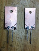
In the picture, you can see my homemade version. A two sided copper clad board was cut into 15 x 30 mm parts. Near the bottom, I cut two narrow slices out of the copper and soldered the Susumu KRL over the gap. Note that this is a long side solder resistor. Two 1 mm holes were drilled and resistor lead were soldered in place. This was repeated on the back side of the board.
The resistors and leads are as close to the bottom as possible so that inductance is kept small. The height of the board is mainly to give surface area for heat transfer and it works pretty well. There is also a hole near the top so that a heat sink can be attached for additional heat transfer. As it sits here, the pcb runs at between 40 and 45 deg C without additional heat sinks. Of course, the ideal would be to have small pcb made professionally with a gold wash and no solder mask to get in the way of heat transfer.
Ok, so enough background, you want to know how they work. In my opinion, they are a very nice step forward. They improve the clarity of the ADA4627 even more and uncover instrument harmonics that were not heard before. For me, this warms the sound and makes it more realistic. But this is just one person's view. I would hope that a few builders, especially those using jfet opamps, will try this and report their impressions.
And one other thing. You need 8 resistors to make a stereo pair. In the US, Mouser is selling 10 of the 0R33 KRL for $3.70. Even if you throw away the extra two resistors, you are getting a quad resistor for about $1.85 each. Compare that with the current Mouser price for the Caddock at $5.47 and you have another reason to try the KRL.
Jac
Last summer, I decided to learn more about resistors and started researching and collecting parts to try. About the same time, George pointed all of us to a thread where diyAudio member EVUL was playing with series/parallel resistors. I found that very interesting.
Let's talk about R3. It is in the main signal path and inside two feedback loops. It seems clear that an improvement in R3 would likely improve sound quality.
R3 is different from other signal path resistors because it needs to be a power resistor. Using Mauro's numbers, the My_Ref has 45W into 8 Ohms. For the standard build, R3=0R47, that's 2.6W in R3. For the evo A, 1.85W. We should be using resistors rated at 4 to 5W to have some safety margin.
In my opinion, power resistors used in audio, typically thick film and metal Oxide, are much weaker performing than the lower power metal film/foil resistors. They have 2 to 3 orders of magnitude worse current noise.
They are also subject to what is sometimes called “power modulation distortion.” Combine the change in resistance with temperature with how hot the resistor gets per watt and you have a PCR (power coefficient of resistance). A change in resistance in the circuit changes the output and that is distortion. More than that, music has loud and soft passages where the power dissipated by the resistor is changing with the music. You can see how this can negatively affect sound.
The Caddock has two orders of magnitude worse current noise than a typical metal film 1/4W resistor. It as a tempco of 200 ppm/C compared to 25 to 100 being typical for 1/4W metal film resistors. The Caddock does have the advantage of being designed for a heat sink. It would be great if we could find metal film resistors with better specs that could handle the power.
Quad resistors, also known as Quartet resistors or series/parallel resistors have some interesting properties. Starting with a description, a quad resistor replaces a single resistor with 4 resistors of the same value in a combined series/parallel package. In other words, 2 strings of 2 resistors in series and the 2 strings in parallel. That results in a resistor that has the same value as the single resistor, but 4x the power rating. Better than that, the theory says that the quad will have 12 dB less distortion than the single resistor.
Because the power rating is 4 times the single resistor, it is possible to use lower power rating resistors with better specs. In the case of R3, I have chosen to use Susumu KRL current sense resistors, specifically part number KRL2012E-M-R330-F-T5 for the 0R33 value used in evo A. This resistor is a foil resistor that is rated at 1W, 50 ppm/C, and should have very good current noise. Combining these into a Quad resistor will give us 4W power rating and, if we design the pcb properly, we should have a good opportunity for heat transfer.
In the picture, you can see my homemade version. A two sided copper clad board was cut into 15 x 30 mm parts. Near the bottom, I cut two narrow slices out of the copper and soldered the Susumu KRL over the gap. Note that this is a long side solder resistor. Two 1 mm holes were drilled and resistor lead were soldered in place. This was repeated on the back side of the board.
The resistors and leads are as close to the bottom as possible so that inductance is kept small. The height of the board is mainly to give surface area for heat transfer and it works pretty well. There is also a hole near the top so that a heat sink can be attached for additional heat transfer. As it sits here, the pcb runs at between 40 and 45 deg C without additional heat sinks. Of course, the ideal would be to have small pcb made professionally with a gold wash and no solder mask to get in the way of heat transfer.
Ok, so enough background, you want to know how they work. In my opinion, they are a very nice step forward. They improve the clarity of the ADA4627 even more and uncover instrument harmonics that were not heard before. For me, this warms the sound and makes it more realistic. But this is just one person's view. I would hope that a few builders, especially those using jfet opamps, will try this and report their impressions.
And one other thing. You need 8 resistors to make a stereo pair. In the US, Mouser is selling 10 of the 0R33 KRL for $3.70. Even if you throw away the extra two resistors, you are getting a quad resistor for about $1.85 each. Compare that with the current Mouser price for the Caddock at $5.47 and you have another reason to try the KRL.
Jac
Attachments
Jac, I would recommend you to start from a more neutral basic setup to make those tests.
Both the Riken and the MK132 are colored and mask details.
Replace them all with RN55/CMF55 or SFR25, including the 50ohm current settings resistors and the 1 ohm resistor.
Then you will have a WAY more neutral sound that will make it easier to appreciate difference in other DUTs
My comments are based on a comparison made on a DAC but they are pretty similar to yours.
What is different is the conclusion, IMHO ADA4627 lacks dynamic impact on bass (you also noticed it) and also lacks a bit of 'presence' effect.
For my taste they are very important point that makes the My_Ref FE sound.
The OPA827 in that regard is MUCH better but still not perfect, seems to introduce too much 'presence' and sometimes sound hardens.
R3 is one of those resistors that I would like to replace but IMHO you're following a weird path... the best replacement would be a power metal foil or power wirewound (anti-inductive design) resistor.
Vishay makes some excellent wirewound but all with iron leads...
Both the Riken and the MK132 are colored and mask details.
Replace them all with RN55/CMF55 or SFR25, including the 50ohm current settings resistors and the 1 ohm resistor.
Then you will have a WAY more neutral sound that will make it easier to appreciate difference in other DUTs
That said, I do feel that the ADA4627 is a noticeable step forward in transparency and, although the listening experience is different, I won't be changing back to LM318 for this system.
My comments are based on a comparison made on a DAC but they are pretty similar to yours.
What is different is the conclusion, IMHO ADA4627 lacks dynamic impact on bass (you also noticed it) and also lacks a bit of 'presence' effect.
For my taste they are very important point that makes the My_Ref FE sound.
The OPA827 in that regard is MUCH better but still not perfect, seems to introduce too much 'presence' and sometimes sound hardens.
The Caddock has two orders of magnitude worse current noise than a typical metal film 1/4W resistor. It as a tempco of 200 ppm/C compared to 25 to 100 being typical for 1/4W metal film resistors. The Caddock does have the advantage of being designed for a heat sink. It would be great if we could find metal film resistors with better specs that could handle the power.
R3 is one of those resistors that I would like to replace but IMHO you're following a weird path... the best replacement would be a power metal foil or power wirewound (anti-inductive design) resistor.
Vishay makes some excellent wirewound but all with iron leads...
Jac, I would recommend you to start from a more neutral basic setup to make those tests.
Both the Riken and the MK132 are colored and mask details....
It's always hard to decide where to start. I acknowledge what I have is not the most neutral, but I have 4+ years experience with it and I wanted to compare the opamp effect in a back to back comparison, on a setup which I have broad experience. I have a bunch of resistors, including those Dales and I will evaluate them in the future.
My comments are based on a comparison made on a DAC but they are pretty similar to yours.
What is different is the conclusion, IMHO ADA4627 lacks dynamic impact on bass (you also noticed it) and also lacks a bit of 'presence' effect.
For my taste they are very important point that makes the My_Ref FE sound.
The OPA827 in that regard is MUCH better but still not perfect, seems to introduce too much 'presence' and sometimes sound hardens....
I picked the ADA 4627 because it appeared to be George's favorite at the time I was ordering. I also have OPA627 which I have good experience with. I'm sure the OPA827 is worth a look as well.
Regarding the dynamic bass and presence, in my opinion, the Quad R3 did a lot to improve that. It may be a combination of things that gets the balance you want.
R3 is one of those resistors that I would like to replace but IMHO you're following a weird path... the best replacement would be a power metal foil or power wirewound (anti-inductive design) resistor.
Vishay makes some excellent wirewound but all with iron leads...
So far, my experience with wirewound, including anti-inductive designs, is that they don't sound natural to me. That said, I'm always open to something new.
Also, forget about Vishay CPF series, a power metal film. In my opinion, they don't live up to their power rating and also sound harsh.
As for quads, this is the second project that I have tried quads to replace power resistors with excellent success. The more research that I did into resistor technology, the more I realized the failings of most power resistor technology. I came to the conclusion that finding a way to use lower power resistors and share the load was the best approach currently available. I didn't invent the quad thing. It is being used in other applications out there.
Regarding the Vishay WSL that you mentioned, it could be fine, but you would still need a quad combination for FE because they don't make anything larger than 1 watt in the resistance range we need.
The WSL and the KRL are both foil SMD series. In fact, although I haven't found any available, the KRL series lists up to 10W versions. The trick to all of these power resistors is heat transfer. In my opinion, the design of the KRL is better for heat transfer and equal or better on other criteria.
Check this out for more details.
Video | Current Sensing Resistors | Susumu International U.S.A. -Specialist in Thin Film Technology-
Jac
One other thing. With the LM318 boards, when I replaced C13 with a jumper, it was less dynamic. It seems to be that DC coupled has plus and minus. Was your 4627 experience DC coupled or with C13 in place?
Jac
Jac
Hi Jac
Thank you for sharing your experience with the Susumu KRL.
try them would be very interesting considering the critical position of that resistance. in terms of listening what consistent improvements have you found?
The cost of these resistors then appears really advantageous having to use 4 series / parallel. Also in the morphology that you have proposed you could also use a sink (maybe recycling that provided for the Caddock).
Giovanni
Hi Giovanni,
The differences I found were improvements in clarity, separation of instruments, and dynamics. The noise floor on quiet passages was lower so you could hear harmonics of string instruments more clearly. This made the instruments feel more present. It also made a small improvement in the width of the sound stage. A small improvement in dynamics was also there, probably due to the lower noise floor.
Dario is correct in that my current build is quite different from more recent BOMs and likely to have some coloration with several carbon film and thick film resistors in the signal path. I would be interested to learn if the Quads are an improvement for you.
This is the second project where I have tried Quads and I found them very worthwhile in both cases. The other project was a 15k Quad for the Impasse pre, so that was a thin metal film power SMD, different than the KRL. From that experience, I can say that the Quad approach is important in the sound quality improvement. That said, the KRL is a very nice design for our R3 situation. I researched a bit further and found that Susumu has a design for higher power KRL but will only make them on special order of 5000 or more.
Recycling the Caddock heat sink would be a good idea. I am running my FE with medium sensitivity, 4 Ohm speakers which means more current and heat in R3 than an 8 Ohm speaker. Driving them pretty hard, I am seeing 15 to 20 degree C above ambient on the Quads without heat sink. That is acceptable, but I would like to reduce that further.
If you decide to try it, a two side, 35 um copper clad board is relatively inexpensive and making the cuts for the resistors is easy. I am considering getting some pcb's made in small quantities because the next project to try Quads requires 12 Quads. I mention this only because I have found I can get the pcb for $1.16 each in 70 um copper (good for heat transfer). That gives you a cost reference for the future.
Jac
Last edited:
Maybe resistors designed for speakers crossovers could do, like Mundorf Supreme, Duelund Graphite or Jantzen Super Res...
They are specifically meant to be placed in series to audio signal, unlike most wirewound resistors
They are specifically meant to be placed in series to audio signal, unlike most wirewound resistors
Last edited:
Very goodHi Giovanni,
The differences I found were improvements in clarity, separation of instruments, and dynamics. The noise floor on quiet passages was lower so you could hear harmonics of string instruments more clearly. This made the instruments feel more present. It also made a small improvement in the width of the sound stage. A small improvement in dynamics was also there, probably due to the lower noise floor.
I have personally used several Z-foils on the signal path with enormous satisfaction.Dario is correct in that my current build is quite different from more recent BOMs and likely to have some coloration with several carbon film and thick film resistors in the signal path.
Recently I placed on the R12 an LDR with fixed value (3k3) with a small circuit with a CCS (LM334 + 10K Trimmer) and an external supply that delivers regulated 5V. This personal variation allowed me a tangible increase in listening performance. The fixed LDR replaced a Z-foil.
I am going to place the Z-foils of 47K and 22K (R5, R6, R8, R9) on the pump.
I will certainly do itI would be interested to learn if the Quads are an improvement for you.
Giovanni
Last edited:
I have personally used several Z-foils on the signal path with enormous satisfaction.
I have a z-foil at R12 on my LXmini amp, but I keep hoping to find something almost as good for less money. Just wishful thinking.
Recently I placed on the R12 an LDR with fixed value (3k3) with a small circuit with a CCS (LM334 + 10K Trimmer) and an external supply that delivers regulated 5V. This personal variation allowed me a tangible increase in listening performance. The fixed LDR replaced a Z-foil.
Now that is interesting. That's the first time I have heard of an LDR in a fixed value.
Jac
Guys I've done this with a few standard variety chipamps. It's a great mod. I've got gobs of little tiny circuit boards to mount the dungeon circuit and ldr on as well as little kits. I'll sell the kits for $7 each to anyone who needs them. Just shoot me a message.
JacNow that is interesting. That's the first time I have heard of an LDR in a fixed value.
Jac
this is my minipcb freely taken from a proposed circuit found on the web.
I believe the author is just udailey.
I used a 7805 in this version + CCS (LM334) + 10K trimmer. Afterwards I removed the 7805 (I did a supply shunt with a TL431 aside) and then I reduced the minipcb size.
The performance is fantastic.

PS: I also use the LDR in my Lightspeed attenuator (homemade)
Last edited:
Sorry udailey...Guys I've done this with a few standard variety chipamps. It's a great mod. I've got gobs of little tiny circuit boards to mount the dungeon circuit and ldr on as well as little kits. I'll sell the kits for $7 each to anyone who needs them. Just shoot me a message.
I could not find the document that refers to your idea and realization.
I apologize.
The document:
Album Archive - Resistor Replacer
Well autocorrect has done it again. Dungeon circuit? No. Regulator circuit.
Yes that is my circuit and pcb. The footprint ends up being almost the same as one ldr.
Yes that is my circuit and pcb. The footprint ends up being almost the same as one ldr.
Obviously everyone is free to do and use whatever they want but as I've already said years ago when this LDR fixed resistor thing come out...
I think this is a terrible idea, how can be a good idea:
LDRs may 'sound' better, AKA pleasant, but not more transparent, IMHO.
They may have a place on very low power applications so to minimize their drawbacks but using them on a power amp...
In those positions you need very thight tolerance resistors, very stable ones, LDRs are not, by a margin.
I think this is a terrible idea, how can be a good idea:
- lenghten circuit paths
- having power lines 'flying' over signal traces
- using a resistor whose light sensitivity, and so resistance value, changes with temperature much more than resistors.
- using a resistor which datasheet says 'Low distortion'...
LDRs may 'sound' better, AKA pleasant, but not more transparent, IMHO.
They may have a place on very low power applications so to minimize their drawbacks but using them on a power amp...
Giovanni, replacing the Howland Current Pump resistors with long leads LDR fixed resistors is simpy the worst place where to use them, anyway.I am going to place the Z-foils of 47K and 22K (R5, R6, R8, R9) on the pump.
In those positions you need very thight tolerance resistors, very stable ones, LDRs are not, by a margin.
Last edited:
Dario,
While we are absolutely on the same page:
I think Giovanni actually wanted to say that he is going to replace the resistors (Susumu RG) with Z-foils in the current pump.
This is what we are doing (one after one) in our little group presently.
Ciao, George
While we are absolutely on the same page:
I think Giovanni actually wanted to say that he is going to replace the resistors (Susumu RG) with Z-foils in the current pump.
This is what we are doing (one after one) in our little group presently.
Ciao, George
Last edited:
- Home
- Amplifiers
- Chip Amps
- My_Ref Fremen Edition - Build thread and tutorial