Just click on the image of the response in this post:
http://www.diyaudio.com/forums/tubes-valves/182813-my-wave-isnt-square.html#post2463423
The overshoot is clearly visible. Last and not least, it is a 1kHz square and time axis is 200us/div, compared to 10us/div I have shown. I hope I do not need to explain such elementary issues.
http://www.diyaudio.com/forums/tubes-valves/182813-my-wave-isnt-square.html#post2463423
The overshoot is clearly visible. Last and not least, it is a 1kHz square and time axis is 200us/div, compared to 10us/div I have shown. I hope I do not need to explain such elementary issues.
Last edited:
More Questions
Thanks again for all your help. Knowledge from practical application really helps. It makes all the studying seem more real.
The coupling cap and NFB are easy enough to change/test. The non linearity problem seems to be a bit more complicated. Considering this could be coming from either stage. I'm considering separating the two stages (see attached). This would allow me to test the gain stage with out the influence of the output stage.
Will this work? Is it a practical test?
I'll try to get to the FR test today. I realize this is an important test. I just haven't got around to setting up the additional hardware.
Is the example of the 'Aikido-like' circuit what I'm looking for?
I realize I need to eliminate the over shoot and ring but how far can you round the edge before comprising HF? I know listening is the final proof.
I'm way to new at this to have standards. For now I'm trying to learn what they should be and how to obtain and measure them
Attachments
Just click on the image of the response in this post:
http://www.diyaudio.com/forums/tubes-valves/182813-my-wave-isnt-square.html#post2463423
The overshoot is clearly visible. Last and not least, it is a 1kHz square and time axis is 200us/div, compared to 10us/div I have shown. I hope I do not need to explain such elementary issues.
No need to get huffy and FWIW I was talking about your square wave not Troncones... 😕 30yrs of engineering experience you don't need to explain anything to me. 🙁
Thanks again for all your help. Knowledge from practical application really helps. It makes all the studying seem more real.
The coupling cap and NFB are easy enough to change/test. The non linearity problem seems to be a bit more complicated. Considering this could be coming from either stage. I'm considering separating the two stages (see attached). This would allow me to test the gain stage with out the influence of the output stage.
Will this work? Is it a practical test?
I'll try to get to the FR test today. I realize this is an important test. I just haven't got around to setting up the additional hardware.
Is the example of the 'Aikido-like' circuit what I'm looking for?
I realize I need to eliminate the over shoot and ring but how far can you round the edge before comprising HF? I know listening is the final proof.
I'm way to new at this to have standards. For now I'm trying to learn what they should be and how to obtain and measure them
You need to look at the TRANSFORMER! (And how it behaves driven by a pentode) Open loop... Until you accept this you are just chasing your tail.. 😀
Last edited:
I don't think square wave test of audio output transformer have much of usefulness, especially taking into account that interpretation of the result is quite difficult (and not so obvious). Square wave composed of leading/falling edge (rise time of several MHz), and DC between them. This is not something large audio transformer supposed to work with. Take for example overshoot. Formula for calculating overshoot is quite complex, but combination of lower leakage inductance and lower distributed capacitance lead to higher overshoot. So, almost perfectly looking 2KHz square-wave on output may be a sign of not so good transformer after all.
You need to look at the TRANSFORMER! (And how it behaves driven by a pentode) Open loop... Until you accept this you are just chasing your tail.. 😀
FWIW I think you are needlessly obsessing over performance issues that on the face of it seem rather minor, and clearly relate to the selection of pentode mode operation with a transformer with insufficient primary inductance, a certain amount of stray capacitance, and leakage inductance.
To figure this out all you need to do is disconnect the feedback loop and do a simple frequency response measurement I think you will find that the LF response is starting to roll off perhaps as high as 100Hz or so with an 8 ohm resistive load applied to the secondary. The transformer introduces phase shift that varies significantly with frequency and particularly at the frequency extremes and may also have a number of mild to severe ultrasonic resonances as well. This makes it difficult to get good square wave performance as the effective group delay is not constant with frequency nor is the amplitude response. You're running up against the physical limitations of a very inexpensive OPT, and I am surprised it does as well as it does.
You don't need to disconnect the driver stage, it is not the culprit here, however you may learn something by verifying its parametric performance. Gain, phase shift, and bandwidth are useful measurements which you can perform with a scope, and a good audio signal generator. (It's response needs to be very flat in the audio range you want to measure or you will need to compensate for amplitude variations in its output - and you should check to make sure the generator is flat before doing any measurements.) Distortion measurements and spectral analysis are very useful if you have a sufficiently good sound card and some way to safely interface it (Pete Milletts box) to the circuit under test.
If this transformer has an option for UL operation I would recommend you give that a shot as well. Power output will be comparable to pentode, and because of local feedback LF performance might improve slightly or not. If LF performance is not really the issue it will tame the pentode highs that might be bothering you. You should also try triode connection if you don't need more than 1.5W or so of output power, transformer performance will be significantly improved on the low end due to the comparatively low rp, and depending on the amount of leakage inductance present HF performance may still be OK.
Since you have already done square wave testing I think it is worthwhile to continue doing so as it will give you a quick indication of changes in performance as a result of my suggestions above, but please also measure the overall frequency response and that of the output stage which you can do by referencing the measurement to the grid of the 6BQ5 without disconnecting anything. Always use a resistive load on the secondary of your OPT.
Last edited:
I'm still here
And trying to keep up.
I haven't read the previous 6 or 8 posts so before anybody repeats themselves let me catch up on my reading. The answerers or at least directions to look my already be noted.
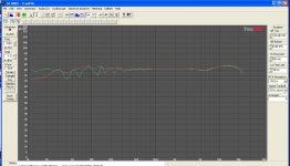
I did a sweep with the only tool I have. You might recognize it. It is designed for speaker analysis. Which I don't think works well for this application.
Tested at 1 watt. The green line is with NFB, the red no NFB. Questioning the results I looked at in and out at 41 hz. The wave shape appears to support what the sweep shows. If I remove the NFB the input sensitivity goes way down and both shapes become flatter (less pronounced) (no photo, sorry). But the output is still distorted.
Once again, let me digest all the great info in the previous posts before I ask my next question.
And trying to keep up.
I haven't read the previous 6 or 8 posts so before anybody repeats themselves let me catch up on my reading. The answerers or at least directions to look my already be noted.
I did a sweep with the only tool I have. You might recognize it. It is designed for speaker analysis. Which I don't think works well for this application.
Tested at 1 watt. The green line is with NFB, the red no NFB. Questioning the results I looked at in and out at 41 hz. The wave shape appears to support what the sweep shows. If I remove the NFB the input sensitivity goes way down and both shapes become flatter (less pronounced) (no photo, sorry). But the output is still distorted.
Once again, let me digest all the great info in the previous posts before I ask my next question.
Attachments
And trying to keep up.
<snip>
If I remove the NFB the input sensitivity goes way down and both shapes become flatter (less pronounced) (no photo, sorry). But the output is still distorted.
Once again, let me digest all the great info in the previous posts before I ask my next question.
Sorry for ignoring the last comment above but is the comment about NFB a typo? The way it is worded seems to imply that with feedback applied gain increases, if so you are applying positive feedback which would explain quite a lot actually. (Apparently even with feedback applied [modest here] there is not quite enough phase shift before the unity gain intercept to cause oscillation. Unusual, but not unheard of) With NFB applied gain relative to the input will decrease and your bandwidth/response flatness/distortion should all improve. (Until you saturate the OPT that is.. 😀 )
Last edited:
Let me add.
I did change the coupling cap to .1 uf. anything larger didn't appear to improve the square wave. I also increased the NFB to about -17dB. Why only -17? I want to keep the input sensitivity at about 1.2v rms. My conclusion is I need to switch to a driver with more horse power. The 6SN7 only has a gain of about 15.5 in this configuration.
The amp does sound better. Or so I thought. Looking at the sweep results I don't see how it could. I didn't sweep before I changed the coupling cap so maybe it alone helped the bass response.
Let me add.
I did change the coupling cap to .1 uf. anything larger didn't appear to improve the square wave. I also increased the NFB to about -17dB. Why only -17? I want to keep the input sensitivity at about 1.2v rms. My conclusion is I need to switch to a driver with more horse power. The 6SN7 only has a gain of about 15.5 in this configuration.
The amp does sound better. Or so I thought. Looking at the sweep results I don't see how it could. I didn't sweep before I changed the coupling cap so maybe it alone helped the bass response.
Please see above post #28 ! What is the answer to the question I posed? 😀
Also note that you are unlikely to be able to get away with much more than 20dB of feedback anyway. I would look at ways to eek out a couple of extra dB of gain from your 6SN7. It actually was a very reasonable choice for this application.
Last edited:
It must be a wording issue. And now as I read it again I can see your point. The output decreases when the NFB is applied. (If I remove the NFB I can reduce the input to get the same output and the input P-P shape is flatter)
I also poorly stated, with or without NFB the shape of the output wave dosn't change.
I also poorly stated, with or without NFB the shape of the output wave dosn't change.
It must be a wording issue. And now as I read it again I can see your point. The output decreases when the NFB is applied. (If I remove the NFB I can reduce the input to get the same output and the input P-P shape is flatter)
I also poorly stated, with or without NFB the shape of the output wave dosn't change.
OK, so it sounds like the feedback is actually negative. Now you really need to go back and open the loop and do a frequency response measurement into an 8 ohm resistive load. All you need is your scope and generator. Set the generator to give you something comfortable like 2Vpp sine wave on your scope at 1kHz. Sweep the generator down in frequency until you find the point where the voltage is now 1.414Vpp - this is your -3dB LF corner, next do the same in the opposite direction to establish your -3dB HF corner. There is little point in going on until you understand the frequency response limitations of your transformer.
Also please assure that you have a reasonable amount of 6BQ5 cathode current which should be in the region of 40mA.
Let me know what you find.. 😀
Thanks Kevin.
That sounds simple enough, even for me.
I really appreciate your patience with Newbies.
That sounds simple enough, even for me.
I really appreciate your patience with Newbies.
I think you are moving quickly in the right direction, and won't be a newbie for much longer. Developing a methodology and doing the work you are doing is a huge step forward.
Note obviously that 1.4V is what I should have posted, those 14mV don't matter much and you don't have that level of resolution on the scope face obviously.. -3dB is the half power point which is just a smidge over 70% of the initial voltage as a reasonable approximation.
You will end up with a pretty good sounding amplifier at the end of this.
I think your transformer has a UL tap on the primary, I'd recommend evaluating this configuration in addition to pentode mode. To prevent HF oscillations a small resistor (220 ohm ought to ok) should be placed right at the screen grid. This should provide better performance with the limited primary inductance of your OPT, and should not significantly reduce output power. (I prefer triode to UL which I generally prefer to pure pentode)
First let me say the posts on this thread have been very helpful. Thank you.
I know it appears I'm obsessing with high performance. What I have learned from this discussion is much more important to me than the performance of this amp. There will be others.
LF -3dB 70hz, HF -3db 55khz (55khz can that be right?)
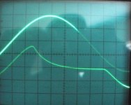
What on the square wave indicated poor LF response, the slope of the line from leading edge to trailing edge?
What else did you see that suggested the OPT was inexpensive?
By the way, my trace was very slightly rotated (low on the right) when I took the photos for my first post.
How did you determine I'm having HF oscillations, from the rise in dB between 10k and 20khz on the RTA sweep?
Should I be able to see these oscillations on the scope? I looked at this range with both sine and square waves and didn't really see anything odd.
The big question, which seems to be the main contribution to limited performance of this amp, is what should the primary inductance be for a pentode?
The bigger question is can you point me in a direction to further study the relationship between primary inductance and the different tube types. I'm presuming this is more related to rp than a specific type of tube. I glanced through M.J.'s Valve Amplifiers and didn't see the topic address directly. More in depth study of resonant circuits?
I will try both UL and Triode connections at some point. I'm trying to learn as much from this test a possible.
I'm going to leave understanding the comment about temporal law violations (post #19) for a much latter date. Much latter.
I know it appears I'm obsessing with high performance. What I have learned from this discussion is much more important to me than the performance of this amp. There will be others.
LF -3dB 70hz, HF -3db 55khz (55khz can that be right?)
What on the square wave indicated poor LF response, the slope of the line from leading edge to trailing edge?
What else did you see that suggested the OPT was inexpensive?
By the way, my trace was very slightly rotated (low on the right) when I took the photos for my first post.
How did you determine I'm having HF oscillations, from the rise in dB between 10k and 20khz on the RTA sweep?
Should I be able to see these oscillations on the scope? I looked at this range with both sine and square waves and didn't really see anything odd.
The big question, which seems to be the main contribution to limited performance of this amp, is what should the primary inductance be for a pentode?
The bigger question is can you point me in a direction to further study the relationship between primary inductance and the different tube types. I'm presuming this is more related to rp than a specific type of tube. I glanced through M.J.'s Valve Amplifiers and didn't see the topic address directly. More in depth study of resonant circuits?
I will try both UL and Triode connections at some point. I'm trying to learn as much from this test a possible.
I'm going to leave understanding the comment about temporal law violations (post #19) for a much latter date. Much latter.
As a rough approximation, you can work out the open-loop LF point as follows:
calculate the load impedance seen at the output anode (i.e. take the load impedance and multiply by OPT turns ratio squared),
calculate the parallel combination R of this with the anode impedance rp,
then LF roll-off is at f = R / (2 pi L), where L is primary inductance.
calculate the load impedance seen at the output anode (i.e. take the load impedance and multiply by OPT turns ratio squared),
calculate the parallel combination R of this with the anode impedance rp,
then LF roll-off is at f = R / (2 pi L), where L is primary inductance.
I'm going to leave understanding the comment about temporal law violations (post #19) for a much latter date. Much latter.
That was a joke about the trace rotation. My apologies, didn't mean to be taken seriously.😀
You're heading down the right path. Experiment with topologies and operating points. Output tubes as well. You'll soon get a pretty good feel for the trade-offs.
LF -3dB 70hz, HF -3db 55khz (55khz can that be right?)
What on the square wave indicated poor LF response, the slope of the line from leading edge to trailing edge?
LF drop 3dB at 70 Hz is too much (may be you meant 17 Hz ?). BTW, no transformer is capable to make good-looking LF square-wave because DC component is too "long". The only transformer capable of transferring DC is a shorted one between primary and secondary - not something you are looking for.
Once again, square-wave is not suitable to test audio transformer.
One test which is useful and can tell something about core construction/material quality is to unbalance idle current of output tubes (+5ma for one and -5mA for another) and load amp with 20 Hz sine-wave at max power. Small cross-over distortions are OK, but core saturation will point to poor material or construction quality.
3dB down at 70Hz is a pretty significant and early roll off, and is due to insufficient primary inductance for pentode mode operation. I would try UL operation as the local feedback should improve low frequency extension at least a little at no significant penalty in output power. Triode would be better still, but at a huge penalty in output power. I would probably go that way anyway.. 😀
- Status
- Not open for further replies.
- Home
- Amplifiers
- Tubes / Valves
- My Wave Isn't Square.