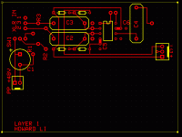
I did this in ExpressPCB's software based on the suggested preamp schematic in the INA217 datasheet. Any suggestions?
I don't know how to fit the labels for the diodes, but I don't think that's a big deal. I've run the rails pretty close to the signal traces but assuming low ripple, the signal traces shouldn't pick anything up - I think. Will anything get past the diodes?
The +/0/- header is going to be roughly where it is now, but I don't know what to do about the balanced output from the chip.
There's a ground plane underneath, but I can't figure out how to get pads that are connected to the ground plane to look different - pin 1 of the input is obviously connected to the plane, and so are the isolated holes adjacent to the chip - they're for the decoupling caps. Last one is the one next to the G on the supply header.
The layout is fairly modular, so I think I can get 4 channels without any problems.
EDIT: Oops. Forgot to connect the via next to the REF pin (pin 5 of the chip).
Attachments
hi
nice preamp chip
I would not use a gnd plane (use gnd pour on top instead)
Don't need and it also can cause some problems and errors.
Needs artwork for bottom gnd plane.
Costs more.
Copy the output circuit from Linkwitz ie psudo XLR output.
Find a way to adjust the gain (pots are OK, but you need a way to calibrate if using stereo) switched resistors or PCB HD bifurcated pin/posts .
Look at this product for other ideas. It uses a early version of that chip. schematic is linked http://www.rane.com/ms1b.html
edit>note their power scheme it is very clever and effective.
hint>use 0 ohm resistors for jumpers on a single layer PCB
What's a ground pour?infinia said:hi
nice preamp chip
I would not use a gnd plane (use gnd pour on top instead)
Look at this product for other ideas. It uses a early version of that chip. schematic is linked http://www.rane.com/ms1b.html
edit>note their power scheme it is very clever and effective.
I'm trying to figure out the schematic but some parts are still losing me.
Thanks for the hint about the jumpers.
454Casull said:
What's a ground pour?
.
When the economy goes south the ground loses all his money. bad bad bad
The empty acrearage is filled in with gnd. poured-in so to speak.
maybe it is a good mike preamp 2 for you
http://www.audiomasterclass.com/arc.cfm?a=giant-killing-$5-mic-preamp-its-secrets-revealed
br Walter
http://www.audiomasterclass.com/arc.cfm?a=giant-killing-$5-mic-preamp-its-secrets-revealed
br Walter
- Status
- Not open for further replies.
