IVX said:And again a riddle An externally hosted image should be here but it was not working when we last tested it.

😎grzechhh said:
Tripath TA0104A without cover
I think that these two black drops on right side is IR2110/3
Hi Charles, I think it can be done with care. Someone explained in another thread that the the Tripath works by idling with many short pulses. But as the audio increases, the frequency drops down progressively. I once had a IR2113 up to about 1Mhz, but the power consumption is up near its maximum capability.phase_accurate said:I don't know if an IR2110 would be capable of sustained driving of the output devices with the Tripath - typical idle frequency higher than 1 MHz.
Regards
Charles
Sergio, your plan sounds good.
Hi All,
IMHO, choice MAX4295 is not so good idea, be cause this chip already contain internal feedback network (data sheet is mute about it, but THD .4 % and power source ripple rejection - 90db however) it will be source of problem with loop stability.
<But how do I connect the feedback signal?> one more problem..
Maximum simplicity? OK.. let's take subwo1 circuit but with lm319 ! You wanna more simplicity? I am long time wondered to use ir2111/2184 & mosfets only for self oscillating topology, IMHO chance is exist, without claim precision of course.
best regards.
Hi IVX, ahh, that is what I figured out with the Texas Instruments equivalent chips.
Where would the LM319 go?
Where would the LM319 go?
http://eu.st.com/stonline/books/pdf/docs/2155.pdf
http://www.national.com/ds.cgi/LM/LM119.pdf
 maybe I have not understood your question?
OOPS - output current for lm319 up to 25mA, in ssanmor circuit this limit is it is dangerous exceeded (30v/500ohm=60mA)!
http://www.national.com/ds.cgi/LM/LM119.pdf
maybe I have not understood your question?OOPS - output current for lm319 up to 25mA, in ssanmor circuit this limit is it is dangerous exceeded (30v/500ohm=60mA)!
Ahh, let me try to ask again. Where in my circuit would the LM319 go?
Hi all,
BTW, I have decided after much though that I can very easily convert my circuit to full bridge. Then concerns over PS pumping from DC offset (200mv without adjustment pot) and low frequencies will be gone. I hope to post it soon.
Hi all,
BTW, I have decided after much though that I can very easily convert my circuit to full bridge. Then concerns over PS pumping from DC offset (200mv without adjustment pot) and low frequencies will be gone. I hope to post it soon.
Hi all,
OK, I have decided that I can easily use my style of p2p circuit construction with the bridge circuit by stacking one IR2113 on top of the other😱 The lower mosfet driver supply and the signal input supply will be common and shorted together by the two pins. The bootstrap supplies will be separate. The four mosfets can be very close together.
Hi IVX,
I think I see where the LM319 goes. Remember also, that it is limited to only 36V besides of the maximum current rating of 25mA.

Hi All,
today i was measured THD (at 100hz in 1Khz bandwidth) for amploiD 3L ( light version ), but not sure in result - how many THD exactly.Measured by PC sound card.
but in_to_out (sound card) THD are .04373%..
regards
today i was measured THD (at 100hz in 1Khz bandwidth) for amploiD 3L ( light version ), but not sure in result - how many THD exactly.Measured by PC sound card.
An externally hosted image should be here but it was not working when we last tested it.
but in_to_out (sound card) THD are .04373%..
regards
Hi IVX,
Either of those figures seems pretty decent. At what output power level is the measurement.
grzechhh,
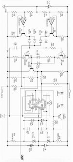
Is that the generator for the triangle reference wave? Looks a little complex.
Either of those figures seems pretty decent. At what output power level is the measurement.
grzechhh,
Is that the generator for the triangle reference wave? Looks a little complex.
about 100w@4ohm, i was said that this caraudio version and maximum simplicity edition with max power about 400w, but i not have car accumulator in my home yet, only 100w transformer 4 diodes and 10000uF (cap at +/-50v - 2200uF!!!!!). At the car THD will be less.
best regards
best regards
grzechhh,
i don't know how many Khz, but slew rate on C16 is 1.3v/uS..not so much beautiful circuit IMO.
best regards
i don't know how many Khz, but slew rate on C16 is 1.3v/uS..not so much beautiful circuit IMO.
best regards
IVX said:grzechhh,
i don't know how many Khz, but slew rate on C16 is 1.3v/uS..not so much beautiful circuit IMO.
best regards
Hmm... You say it isn't beautiful, but when I read this http://www.crestaudio.com/media/pdf/st_cutsheet.pdf
ST2000:
at 1000W/4Ohm (full bandwidth 20-20000Hz) - 1% THD+N,
I think that is good parameters, with your circuit will be possible to get smaller distortions or comparable ?
Hi grzechhh,
i just mean that circuit is much complicated. Looks better and nice working such as ssanmor's triangle generator. I'm still do not try to build full range class D, but it's in my plans (i hope so far). 1 % THD is not for me yet, therefore i'll be trying the discrete driver and self oscillating topology.
best regards.
<Maybe some PNP level shifters with parallel coupling Cs for speed would do the trick.>-just add cap! good idea also works perfectly - i checked simulation. THX Charles! 😎
i just mean that circuit is much complicated. Looks better and nice working such as ssanmor's triangle generator. I'm still do not try to build full range class D, but it's in my plans (i hope so far). 1 % THD
is not for me yet, therefore i'll be trying the discrete driver and self oscillating topology.best regards.
<Maybe some PNP level shifters with parallel coupling Cs for speed would do the trick.>-just add cap! good idea also works perfectly - i checked simulation. THX Charles! 😎
Hi IVX,
Maybe capacitors across the gates of CMOS are not really needed in DT circuits. The simulation shows very little jump in voltage with a 1N4148.
Here is a question. If the output has a 1.5% difference in amplitude between the + and - peaks, does that mean there is 1.5% distortion?
Best Regards
Maybe capacitors across the gates of CMOS are not really needed in DT circuits. The simulation shows very little jump in voltage with a 1N4148.
Here is a question. If the output has a 1.5% difference in amplitude between the + and - peaks, does that mean there is 1.5% distortion?
Best Regards
Attachments
Hi subwo,
<Maybe capacitors across the gates of CMOS are not really needed in DT circuits.-ok, maybe, but resistor for adjusting must be 100-200k, it's always worse protected from EMI. Don't touch such gates of CMOS by scope probe however.
< If the output has a 1.5 % difference in amplitude between the + and - peaks, does that mean there is 1.5 % distortion? - maybe it's a DC offset?
I wanna find any idea about discrete driver solution, especially voltage shifter from low side to flying high side(i was try bs108 n-mosfet .2A). Gate drive MAX5048 (12nS@1.5/7A-1nF ) probably.
Best regards.
<Maybe capacitors across the gates of CMOS are not really needed in DT circuits.-ok, maybe, but resistor for adjusting must be 100-200k, it's always worse protected from EMI. Don't touch such gates of CMOS by scope probe however.
< If the output has a 1.5 % difference in amplitude between the + and - peaks, does that mean there is 1.5 % distortion? -
maybe it's a DC offset? I wanna find any idea about discrete driver solution, especially voltage shifter from low side to flying high side(i was try bs108 n-mosfet .2A). Gate drive MAX5048 (12nS@1.5/7A-1nF ) probably.
Best regards.
Hi IVX,
< If the output has a 1.5 % difference in amplitude between the + and - peaks, does that mean there is 1.5 % distortion? - maybe it's a DC offset?
That was one of my thoughts until I tried it with the input at 0 volts. What I determined is that the current mirror was the cause. Instead of adding a resistor in series and a capacitor in parallel with the the base / collector connection of the control side of the current mirror to keep it more at constant current output, I removed it from the circuit. I don't want to just add more parts whenever there is a design flaw. I usually backstep to find a better way.
<I wanna find any idea about discrete driver solution, especially voltage shifter from low side to flying high side(i was try bs108 n-mosfet .2A). Gate drive MAX5048 (12nS@1.5/7A-1nF ) probablyBest regards. .>
I considered a small mosfet like that driving a low side mosfet driver. It is a possible experiment. I think the pull up resistor on the gate can be bootstrapped instead of connecting it to the positive rail. If it can be sucessfully bootstrapped, that could make a big difference on rise time because the pull up resistor could be much lower in value.
Best Regards.
< If the output has a 1.5 % difference in amplitude between the + and - peaks, does that mean there is 1.5 % distortion? - maybe it's a DC offset?
That was one of my thoughts until I tried it with the input at 0 volts. What I determined is that the current mirror was the cause. Instead of adding a resistor in series and a capacitor in parallel with the the base / collector connection of the control side of the current mirror to keep it more at constant current output, I removed it from the circuit. I don't want to just add more parts whenever there is a design flaw. I usually backstep to find a better way.
<I wanna find any idea about discrete driver solution, especially voltage shifter from low side to flying high side(i was try bs108 n-mosfet .2A). Gate drive MAX5048 (12nS@1.5/7A-1nF ) probablyBest regards.
.>I considered a small mosfet like that driving a low side mosfet driver. It is a possible experiment. I think the pull up resistor on the gate can be bootstrapped instead of connecting it to the positive rail.
If it can be sucessfully bootstrapped, that could make a big difference on rise time because the pull up resistor could be much lower in value. Best Regards.
Hello subwo,
< If it can be sucessfully bootstrapped, that could make a big difference on rise time because the pull up resistor could be much lower in value.> I'm still so stupid.. please attach IMG for explanation.
Best regards.
< If it can be sucessfully bootstrapped, that could make a big difference on rise time because the pull up resistor could be much lower in value.> I'm still so stupid.. please attach IMG for explanation.
Best regards.
- Status
- Not open for further replies.
- Home
- Amplifiers
- Class D
- My very first Class D pwm (switching) amplifier.