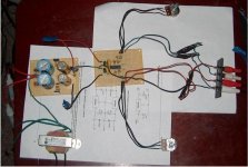
from "The Audiophile's Project Sourcebook" page 65 fig 3.1. I omitted all the RIAA circuitry (already have a RIAA board) and just built the preamp section twice for stereo. the board on the right is the preamp and the board on the left is the psu (just in case someone doesn't know by looking).
for the preamp i used 2/4 of a TLO74 opamp chip, and just grounded the input pins of the two unused ones. all caps in the signal path are tantalum and all resistors in the signal path are metal film. level adjustment is done via the two 20K pots at the top and bottom of the picture (one adjusts left channel the other adjusts the right)
my assessment:
since the only measuring instruments i currently have at my disposal are a VOM and my ears, i apologize for not being able to give a more objective analysis and measurements. my opinion is it sounds very nice and worth building. highs are crisp and accurate, mids are clean and lows are powerful and smooth. no perceivable hum or noise or buzzing issues, so im assuming PSRR is very good. a very wide range of level adjustment is possible with this circuit, from off to making a receiver thats set on 1 sound like its on like 6 or 7 in volume.
this is part of a larger project that will also include source selection, tone controls, level indicators and a RIAA board all in one box.
all comments, suggestions, questions and observations welcome.
Attachments
TBH from looking at the PCB and summarizing (havent seen the book) there isn't much going on here. An opamp based preamp is a pretty simplistic thing.
There are easy improvements to make - the first would not be using tantalum capacitors. Polyester are much better here for coupling purposes. If they are small value capacitors used for bandwidth limiting, polypropylene work very well. Stick with ceramics for decoupling.
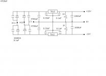
The PSU is easily improved - instead of using the 7815/7915 pair, use LM317/337 with the adjust pin bypassed by a 10uF capacitor.
The TL074 opamp can be easily replaced especially if you are only using two opamps - NE5532 works well, or OPA2134 if you prefer a FET based opamp.
A few projects you might wish to check out:
http://sound.westhost.com/project02.htm (for reading)
http://sound.westhost.com/project88.htm
http://sound.westhost.com/project97.htm
http://sound.westhost.com/project05b.htm
There are easy improvements to make - the first would not be using tantalum capacitors. Polyester are much better here for coupling purposes. If they are small value capacitors used for bandwidth limiting, polypropylene work very well. Stick with ceramics for decoupling.
The PSU is easily improved - instead of using the 7815/7915 pair, use LM317/337 with the adjust pin bypassed by a 10uF capacitor.
The TL074 opamp can be easily replaced especially if you are only using two opamps - NE5532 works well, or OPA2134 if you prefer a FET based opamp.
A few projects you might wish to check out:
http://sound.westhost.com/project02.htm (for reading)
http://sound.westhost.com/project88.htm
http://sound.westhost.com/project97.htm
http://sound.westhost.com/project05b.htm
Hi jaycee, thanks for your reply!
yes i know. this was really my first diy audio project building from scratch so i went for something simple. also i needed something like this because the signal from my ipod does a poor job at driving the input to one of my vintage receivers, hence the need for the opamp to boost the signal.
actually that was a typo. i used the tantalums for opamp decoupling, and in one place in the signal path where the schematic specifically called for it. all the rest are garden variety ceramics i had on hand, so yeah i realize theres much room for improvement here. if i decide to build a six channel version of this for my home theater, then i will definitely take your advice and invest in some boutique caps. but as it is and for what i'm using it for, it sounds just fine to me the way it is.
i thought the 317 was an adjustable regulator? i was going for a +/- 15V split supply hence my reason for using the 78/79 series so could you explain why 317/337 is better here?
good to know and thanks for the input. i used the TLO74 simply because i had a few on hand and also because Slone recommended them as a possible choice for this design.
thanks, i most certainly will check these out.
jaycee said:TBH from looking at the PCB and summarizing (havent seen the book) there isn't much going on here. An opamp based preamp is a pretty simplistic thing.
yes i know. this was really my first diy audio project building from scratch so i went for something simple. also i needed something like this because the signal from my ipod does a poor job at driving the input to one of my vintage receivers, hence the need for the opamp to boost the signal.
jaycee said:
There are easy improvements to make - the first would not be using tantalum capacitors. Polyester are much better here for coupling purposes. If they are small value capacitors used for bandwidth limiting, polypropylene work very well. Stick with ceramics for decoupling.
actually that was a typo. i used the tantalums for opamp decoupling, and in one place in the signal path where the schematic specifically called for it. all the rest are garden variety ceramics i had on hand, so yeah i realize theres much room for improvement here. if i decide to build a six channel version of this for my home theater, then i will definitely take your advice and invest in some boutique caps. but as it is and for what i'm using it for, it sounds just fine to me the way it is.
jaycee said:
The PSU is easily improved - instead of using the 7815/7915 pair, use LM317/337 with the adjust pin bypassed by a 10uF capacitor.
i thought the 317 was an adjustable regulator? i was going for a +/- 15V split supply hence my reason for using the 78/79 series so could you explain why 317/337 is better here?
jaycee said:
The TL074 opamp can be easily replaced especially if you are only using two opamps - NE5532 works well, or OPA2134 if you prefer a FET based opamp.
good to know and thanks for the input. i used the TLO74 simply because i had a few on hand and also because Slone recommended them as a possible choice for this design.
jaycee said:
A few projects you might wish to check out:
http://sound.westhost.com/project02.htm (for reading)
http://sound.westhost.com/project88.htm
http://sound.westhost.com/project97.htm
http://sound.westhost.com/project05b.htm
thanks, i most certainly will check these out.
i have noticed something interesting this circuit does.
ground both inputs. turn both level controls to any setting you want, turn volume on receiver/power amp up to max. then, there is a very very slight mains hum in the woofer. i mean its so slight i have to actually stick the side of my head into the woofer cone to allow my ear to detect it. but sure enough, its hum. heard hum enough times to recognize it the instant i hear it. unfortunately.
whats confusing me is this. after disconnecting my circuit from the mains, the hum continues unchanged until the filter caps in the PSU discharge through the bleeder resisters enough to turn off the opamp ... which in my case is about four seconds. then the hum goes away completely.
so in other words the hum isn't coming from the trafo, because it continues when the primary is unplugged from the mains. it can't be being injected in the power amp or the rca cable from the power amp to my circuit, because the hum stops when the circuit is shut down.
so whats happening? regulator noise? hum pickup by the grounding system or some component on the circuit board? i mean this problem is barely noticible and is undetectable (to me) other than in the condition i described above, so its not like im in a hurry to fix it or anything.
just curious as to whats making it behave like that.
just switched to all sheilded cable for external signal lines.
situation unchanged. perhaps use shielded cable for the lines to the pots too? just figured i'd see some sort of improvement if i was on the right track.
situation unchanged. perhaps use shielded cable for the lines to the pots too? just figured i'd see some sort of improvement if i was on the right track.
Hum can come from GROUND rail.
Can also be because TRafo is too close to input. But this is not in your case.
It is important to keep the INPUT ground 0V rails separate from other components that connect to ground.
Input ground should have a separate wire/rail to the Common 0 Volt point of your both regulators.
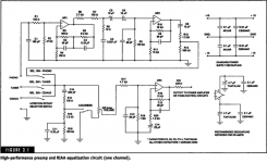
In the figure this is:
- the GND of Volume Pot
- the point below R18, 1 Mohm
Other grounded components, like Load connected to Output, Supply filter caps should have another wire to Regulators 0 Volt point.
Regarding opamps:
For this application, a line preamplifier, you need not to use any other opamps than TL071,TL072, TL074.
They are good enough both regarding low noise, low distortion.
As slone mentions the RIAA part have very low distortion with these JFET opamps.
There are no other opamps that can give this adequate audio quality for same price.
I attach schematic, so people can follow this project better.
Regards
Lineup
Can also be because TRafo is too close to input. But this is not in your case.
It is important to keep the INPUT ground 0V rails separate from other components that connect to ground.
Input ground should have a separate wire/rail to the Common 0 Volt point of your both regulators.
In the figure this is:
- the GND of Volume Pot
- the point below R18, 1 Mohm
Other grounded components, like Load connected to Output, Supply filter caps should have another wire to Regulators 0 Volt point.
Regarding opamps:
For this application, a line preamplifier, you need not to use any other opamps than TL071,TL072, TL074.
They are good enough both regarding low noise, low distortion.
As slone mentions the RIAA part have very low distortion with these JFET opamps.
There are no other opamps that can give this adequate audio quality for same price.
I attach schematic, so people can follow this project better.
Regards
Lineup
Attachments
Originally posted by gain
yes i know. this was really my first diy audio project building from scratch so i went for something simple.
Good idea 😉
Originally posted by gain
actually that was a typo. i used the tantalums for opamp decoupling, and in one place in the signal path where the schematic specifically called for it. all the rest are garden variety ceramics i had on hand, so yeah i realize theres much room for improvement here. if i decide to build a six channel version of this for my home theater, then i will definitely take your advice and invest in some boutique caps. but as it is and for what i'm using it for, it sounds just fine to me the way it is.
Tants have a very bad rep for doing nasty things when they get old and wobbly. For decoupling, good electrolytics are OK, and ceramics are apparently preferred over polyester etc because of their better response at HF - mylars as Slone showed also work well.
For signal coupling there is polyester and then electrolytic - some would say that electrolytics dont belong in the signal path, but sometimes it is neccesary and IMO, preferable to tantalums. Polypropylene or polystyrene capacitors are preferred for filters and compensation because they hold their tolerance well.
Originally posted by gain
i thought the 317 was an adjustable regulator? i was going for a +/- 15V split supply hence my reason for using the 78/79 series so could you explain why 317/337 is better here?
LM317/337 has a lower noise output than the 78/79 series, especially when the adjust pin is bypassed with a capacitor. They aren't much more expensive, and there is only minimal extra work in using them, so it is worth it.
Originally posted by gain
i used the TLO74 simply because i had a few on hand and also because Slone recommended them as a possible choice for this design.
TL07* is fine for experimenting, they are cheap enough 😉 I can't comment as to why Slone recommends them, possibly because this is a "beginner" project and the TL's are an available and cheap FET input op-amp.
Originally posted by gain
thanks, i most certainly will check these out.
Check out Rod's website in general - there is loads of great projects and articles to be had there! It certainly helped me a lot when I was first getting into audio electronics.
Hey lineup, good to see you again. thanks for your input on this.
so just like in a power amp eh? good to know and i was actually considering running separate wires for the input/signal ground and the ground the opamp decouple caps connect to if i ran into a serious hum problem. but this hum is so so very slight as to be unnoticeable except at max volume with no sig applied, so i'm trying to decide if its worth the effort. probably will do it just for experimentation purposes. and to get into good construction habits.
yeah i'm happy with the sound of the '74. i'm not exactly a golden ear dude either tho so it may be making noise and/or nonlinearities that i can't perceive (nor measure because i dont have a scope ... yet)
thanks for attaching the schematic. i was going to but wasn't sure about copyright issues so thats why i didn't.
lineup said:Hum can come from GROUND rail.
Can also be because TRafo is too close to input. But this is not in your case.
It is important to keep the INPUT ground 0V rails separate from other components that connect to ground.
Input ground should have a separate wire/rail to the Common 0 Volt point of your both regulators.
In the figure this is:
- the GND of Volume Pot
- the point below R18, 1 Mohm
Other grounded components, like Load connected to Output, Supply filter caps should have another wire to Regulators 0 Volt point.
so just like in a power amp eh? good to know and i was actually considering running separate wires for the input/signal ground and the ground the opamp decouple caps connect to if i ran into a serious hum problem. but this hum is so so very slight as to be unnoticeable except at max volume with no sig applied, so i'm trying to decide if its worth the effort. probably will do it just for experimentation purposes. and to get into good construction habits.
lineup said:
Regarding opamps:
For this application, a line preamplifier, you need not to use any other opamps than TL071,TL072, TL074.
They are good enough both regarding low noise, low distortion.
As slone mentions the RIAA part have very low distortion with these JFET opamps.
There are no other opamps that can give this adequate audio quality for same price.
I attach schematic, so people can follow this project better.
Regards
Lineup
yeah i'm happy with the sound of the '74. i'm not exactly a golden ear dude either tho so it may be making noise and/or nonlinearities that i can't perceive (nor measure because i dont have a scope ... yet)
thanks for attaching the schematic. i was going to but wasn't sure about copyright issues so thats why i didn't.
Jaycee,
thanks for your reply, some really good info in there.
regarding the tantalums ... didn't realize they deteriorated in such a manner with age. i will seriously consider using good quality electrolytics or polyester instead as you recommend. you may have just saved me who knows how many hours of frustration and/or grey hair genesis in the future debugging circuits with 'wobbley' tants so i appreciate you telling me this fact very much.
also very good to know about the better noise performance of the 317/337 series regulators. whats the normal way to set these up? wire them up like a normal adjustable regulator, then 'adjust' them to 15V (or whatever you need) then measure the resistance you have the pot set to and replace the adjustment pot with a fixed R? will research PSU's that use 317/337 for fixed supplies for design ideas, thanks.
i spent some time on Rod's website last night and yes it does indeed have a LOT of good projects and info. planning on reading more just as soon as i have some free time.
thanks again Jaycee and take care.
just to clarify, i did not implement the RIAA section of schematic lineup posted. iow, i implemented the bottom part of the schematic only, not the top, so my comments apply to that section (preamp section)
just had it fired up on bench with ipod on the input and a '70s ish receiver on the output. top rail was drawing 7.12mA and bottom rail was drawing 7.08mA. adjusting the level controls (with signal applied) from off to max did not make the readings change at all, or at least not enough for my meter to detect. this measurement surprised me somewhat, as i was expecting at least a little increase in current with increases in the level controls (and hence signal output levels). does this measurement and behavior look normal to you more experienced guys?
sounded good though. i tell ya, this thing can make that old vintage receiver really bump in a big way. much more intensely than with the ipod or cd player connected directly. for ex, i knocked two picture frames off the wall in the living room last night with the receiver on like 6, and this receiver has never done anything like that at all before, even on 10!
another thing that is confusing me a little is the fact that both my trafo and both regulators in the psu are running warm. i mean, i can put and keep my fingers on them for any length of time no prob without any pain, but they are noticeably warmer than ambient.
the trafo is rated for 500mA and the datasheet says the regulators can handle up to 1A, so i would think that since my circuit is only drawing ~7mA (plus ~15mA through the bleeder resistors) per rail everything in the psu should be running as cool as a cucumber. yet this is not so.
the trafo is rated for 500mA and the datasheet says the regulators can handle up to 1A, so i would think that since my circuit is only drawing ~7mA (plus ~15mA through the bleeder resistors) per rail everything in the psu should be running as cool as a cucumber. yet this is not so.
gain said:
also very good to know about the better noise performance of the 317/337 series regulators. whats the normal way to set these up? wire them up like a normal adjustable regulator, then 'adjust' them to 15V (or whatever you need) then measure the resistance you have the pot set to and replace the adjustment pot with a fixed R? will research PSU's that use 317/337 for fixed supplies for design ideas, thanks.
You can calculate it. Look at the LM317 data sheet to see how. It doesn't have to be precise, eg 14.8v or so will do, and the negative supply doesnt have to match exactly either. "close enough" is good enough 🙂
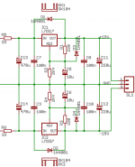
I used 220R between out and adjust, and 2K4 between adjust and ground, with a 10uF capacitor in parallel between adjust and ground.
Here's how mine works. Before the 33 ohm resistors on the left is connected to the power supply for my LM3886 based power amp (+25 and -25v supplies with 2x4700uF capacitance per rail). You would replace this as appropriate. I'd probably stick 1000uF per rail before the resistors, and decrease the resistors to say 4.7 ohm 1W devices.
Attachments
- Status
- Not open for further replies.
- Home
- Amplifiers
- Solid State
- My version of a Slone preamp