The issue I have is that one side of the stereo circuit has a bias point between the two triods of about -0.6V as expected. However the other side has a bias of only -0.27V, and it settles to this value over at least 30seconds, where as the other settles very quickly. Everything points to the fact that the tube is on its way out. The CCS seems to be working OK as the voltage drop across the cathode resistor is the same for both sides. The point is the circuit has been running for only about 8 Months, and the tubes were NOS. These tubes should have a life of at least 5 years. Any ideas as to what might have damaged the tube in such a short time. The problem moves with the tube when I switch them over, so its definitely the tube that’s at fault.
I was thinking that possably tying the heater to earth was creating too much of a potential difference between the cathode and the heater.
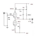
Is 15mA at a +B of 50V pushing this tube to hard ?
Is it possible that the tube is just a dud?
This was my first tube circuit so I am a little worried that I got something wrong have destroyed my precious Tubes. As a matter of interest, the tone of the faulty side doesn’t seem to have appreciably altered, this is suprising as I have found that even a relatively small change in bias point alters the tone of my Sovteck 6922 valves very noticably.
Any ideas would be gratefully received.
Shoog
I was thinking that possably tying the heater to earth was creating too much of a potential difference between the cathode and the heater.
Is 15mA at a +B of 50V pushing this tube to hard ?
Is it possible that the tube is just a dud?
This was my first tube circuit so I am a little worried that I got something wrong have destroyed my precious Tubes. As a matter of interest, the tone of the faulty side doesn’t seem to have appreciably altered, this is suprising as I have found that even a relatively small change in bias point alters the tone of my Sovteck 6922 valves very noticably.
Any ideas would be gratefully received.
Shoog
Attachments
By bias point, do you mean the grid-to-cathode voltage?
It looks like you're running only 45 volts across each of the tubes. That's really, really low and in a regime where small drifts in tube characteristics (especially leakage currents) can have profound results. Have you tried going up to 80 volts or so?
Other normal lifetime issues- do the tubes warm up before B+ is applied? Are they run with heaters on for extended periods without B+?
Your right on the voltages only been about 45V. A little low, but these valves do work as low as 35V without to much trouble. I could consider a voltage doubler circuit to give me something like 90V.
Yes I do mean the Grid to Cathode voltage.
The supply is semiconductor, so yes the +B does get applied before the tubes fully warm up. Still this hasn't presented the same problem on my Valve buffered Gainclone, which has been running for longer (the CCS is replaced with a 10K cathode resistor in this circuit). I know that this is a real potential problem, but many people don't seem to be running into it with similar low volatge circuits.
I looked back at when I got the valves and it turns out they have only been running for 4 months. They came as a matched pair of NOS, so they should certainly have been reading the same at the start - which if my memory serves me - they were.
Any more ideas, or sujestions.
Shoog
Well, NOS is no guarantee that one of them isn't a little gassier than the other. Or has more grid leakage for whatever reason. You're pretty much stuck in a grid bias region where, to be stable, your tubes would have to be burned in and selected. That's fine if you bought a few dozen tubes, not so fine if you didn't.
Thanks for that.
Do you think then that its just natural variation and that the tube has stabalised and will not deteriate significantly in the near future?
As I said before the difference doesn't seem to be effecting the sound significantly (which really suprises me), so I will probably leave as is and see if it fails any time soon. What I was most concerned about was if I had made some fundamental design error which would kill any tube, and given your cavets about low voltage and cathode stripping, this doesn't seem to be what you are indicating.
I am toying with the idea of a different, higher voltage line stage to compare.
Thanks
Hi again,
Just thinking about things after my last posting. I had noticed that the Input pot had been getting a bit poppy recently. This would sujest that Grid leakage is part of the problem.
Do you think that an input blocking cap would help? If so It could be a really good quality, low value because of the high input impedence.
Shoog
Poppy pots are often an indication of grid leakage. With the wiper at midpoint, check the grid's DC voltage. If it's anything but zero, you've got some grid current going on. That's not uncommon at very low bias voltages. If so, absolutely capacitively couple the input.
I tried capacitively coupling the input (after the pot) and the mid point between the tubes shot up to -8V. Not good.
I therefore presume that I will still need to reference the grid to earth via a very high value resistor- say 500K.
Thanks for the input.
Shoog
I therefore presume that I will still need to reference the grid to earth via a very high value resistor- say 500K.
Thanks for the input.
Shoog
Yes, if you capacitively couple, you absolutely need a ground reference. Use a 470K to 1M resistor from the grid to ground. Size the coupling cap to give you a 3dB down point a decade lower than the lowest frequency of interest.
Its going to be a fiddly job to do the modifications, but i'll try them tonight.
Thanks for the excellent advise.
Shoog
Thanks for the excellent advise.
Shoog
I added the input blocking cap with a 1megohm resistor to ground. The pot is now quiet.
I then measured the voltage on the grid. The good tube measured 0.056V and the bad tube measured 0.958V. How bad is that?
Its all still playing well, but I have a bad feeling that that tube is not long for this world. Into every life a little rain must fall.
Shoog
I then measured the voltage on the grid. The good tube measured 0.056V and the bad tube measured 0.958V. How bad is that?
Its all still playing well, but I have a bad feeling that that tube is not long for this world. Into every life a little rain must fall.
Shoog
When I get a replacement tube, I will probably drop the current to about 10mA and also remove the blocking cap. Even though it protects my pot it smudges the sound somewhat.
Thanks for all the help.
Shoog
Thanks for all the help.
Shoog
I have spent the day fault finding the circuit. I made a huge mistake in the first place in that The mid point of the two triods is at +1.0V and not the expected -1.0V. I must have taken the initial readings with the probes the wrong way round. This would account for the grid leakage and why shifting the bias point had very little effect on the sound (its amazing it made any sound at all).
Try as I might tweeking the rail voltages just won't move it into the correct region. You would need the top tube to be working at about 10V to get it close. I am going to have to work out a method of referencing the Midpoint to -1.0V
Wish me luck.
Shoog
Try as I might tweeking the rail voltages just won't move it into the correct region. You would need the top tube to be working at about 10V to get it close. I am going to have to work out a method of referencing the Midpoint to -1.0V
Wish me luck.
Shoog
In the 'olden' days, passive components have very high tolerance and the tubes just run comfortably with it.
Do you check for white powder at your tubes?
Do you check for white powder at your tubes?
Hi there,
My last statement was complete rubbish. My head has been fried by fault finding this circuit-and guess what, no fault, just a doddy tube on its way out. The man I got it off has offered to replace it- Very decent.
I have reduced the current to 7mA as I feel the 16mA was probably pushing it a bit hard, and helped the tube along.
If anyone is interested I can post a fully updated working schematic of this circuit.
Shoog
and guess what, no fault, just a doddy tube on its way out.
After getting it replaced it was fine?
Sometimes NOS aint really NOS after all.. I knew the tubes were suspiciousDo you check for white powder at your tubes?
Yes I had an old tube lying around and it works fine.
New Old Stock, like new tubes are prone to failure. Some of the new Chinese tubes have an almost 50% failure rates( so I have been told). I certainly have bought at least one brand new tube which failed on switch on. If I wanted reliability I would have to stick to silicone, but thats not what its about - is it!
Shoog
Hi,
Shoog,
16mA through the 6DJ8s is indeed a bit tough on the tubes especially on the Chinese ones...
All of those I've seen so far are 6N1-P of sorts but don't get me started on that.
Anyways, as SY pointed out, most pots will start to become noisy at some point with DC present on their wiper.
A switched attenuator won't have this problem, you can then do away with the extra input coupling cap and ground reference resistor and things will start to sound much better still.
Upping the B+/- to at least 90V will allow the CCSed follower to really shine and if it were to be me I'd put a bleeder resistor of roughly 100K behind the output coupling cap; you should notice an increase in dynamic range this way and at the very least no DC will develop across the cap when nothing is connected to the output.
The 3K9 gridstopper seems a little high to my taste, lowering the value could yield better highs IME and the component should be a carbon film with the tail end as close to the grid as you possibly can get it it.
Cheers, 😉
- Status
- Not open for further replies.
- Home
- Amplifiers
- Tubes / Valves
- My tubes are going down. HELP !!!!