Hi everyone,
I need your help again guys. I am designing a pcb for the TDA7293 chipamp and I have a few questions so far.... (I don't want to end up burning the chip) 🙂
In the schematic,
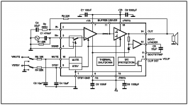
1. What is the working voltage of C5 (22uf Bootstrap Capacitor)
2. How do I implement the use pin 5 (Clip Detect)?
Planned psu is +/-50V @ 10A.
Thank you in advance!
Regards,
JojoD
I need your help again guys. I am designing a pcb for the TDA7293 chipamp and I have a few questions so far.... (I don't want to end up burning the chip) 🙂
In the schematic,
1. What is the working voltage of C5 (22uf Bootstrap Capacitor)
2. How do I implement the use pin 5 (Clip Detect)?
Planned psu is +/-50V @ 10A.
Thank you in advance!
Regards,
JojoD
Attachments
Hi!
Take a look at this document (in German, but the circuit and PCB details might be very helpfulk):
A100 TDA7293 amp
According to this, and the parts description on Schuro.de, you should use a 25V - 63V cap for C5 (C7 in the A100 circuit).
I cannot help you with clipping detection, since the designer of the A100 chose to omit it...
Hope this helps,
Arndt
Hi!
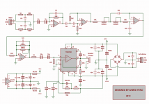
I wanna make a Bridge TDA7293 200watt subwoofer amplifier with a low pass filter by TL074 with bass control and volume control. Please can anyone send me a pcb and shametic circuit diagram of such amplifier? Thanks.
I wanna make a Bridge TDA7293 200watt subwoofer amplifier with a low pass filter by TL074 with bass control and volume control. Please can anyone send me a pcb and shametic circuit diagram of such amplifier? Thanks.
Hi!
I wanna make a Bridge TDA7293 200watt subwoofer amplifier with a low pass filter by TL074 with bass control and volume control. Please can anyone send me a pcb and shametic circuit diagram of such amplifier? Thanks.
Attachments
Make sure those 100nf decoupling capacitors are as close to 7293 power pins as possible.
I had trouble with mine oscillating on the output.
I had trouble with mine oscillating on the output.
The feedback resistor needs to be as close to chip as possible.
Mine was a fair distance away and the chip oscillated.
Mine was a fair distance away and the chip oscillated.
- Status
- Not open for further replies.
- Home
- Amplifiers
- Chip Amps
- My TDA7293 project... please help