I have been doing a lot of reading about this Class D chip. I decided that the EVM was a little expensive and I was not a big fan of the EVM pcb. I had pleanty of free time so I decided to take a shot at making my own pcb.
The pcb was made in Eagle and checked with Viewplot.
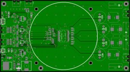
It pretty much follows the EVM design with only a few differences.
Minor movement of components
Mounting for Intel P4 heatsink
Screw Terminals vs RCA & Banana Plugs
Please have a look at the layout and give feedback. Thank You.
The pcb was made in Eagle and checked with Viewplot.
It pretty much follows the EVM design with only a few differences.
Minor movement of components
Mounting for Intel P4 heatsink
Screw Terminals vs RCA & Banana Plugs
Please have a look at the layout and give feedback. Thank You.
Attachments
After checking the board and schematic a few more times I will order 5 prototype pcb's and assemble. Hopefully it will work with good results. I made sure that the SMT inductors had very high saturation currents (21A). Hopefully the build will have good results.
The default of Fosc is 4Mhz. The EVM uses the default master. Do you see any issues with this? The PCB has the option to add a resistor to change the frequency.
wait what? switching freq. won't be anywhere near that, you know that right?
with similar IC, tas5161 its around 380k, if you use tas3308 as I would
with similar IC, tas5161 its around 380k, if you use tas3308 as I would
I may need some adjustments due to the larger heatsink and extended traces in the current path, but the interference should be fairly low. After testing I would also like to make a 2.1CH and 4CH revision. Theis BTL/PBTL setup will be tested with a PA setup and also a home. The SMPS will supply 48V@450W.
Been a little busy with work but I managed to order 2 PCB's. They should be here in a couple weeks and if they look good I will order some components. I will upload high rez scans when I get them.
Well after life kicked my *** for several months, I am back at it. The PCB needs some updates and I need to triple check the schematic again but I still plan to make this thing look and sound awesome.
Hi, I also designed a pcb for the tas5630(b) and would love to see your assembled product. Please keep us up to date.
Here're some pics of mine: http://www.diyaudio.com/forums/class-d/87913-class-d-amp-photo-gallery-66.html
Here're some pics of mine: http://www.diyaudio.com/forums/class-d/87913-class-d-amp-photo-gallery-66.html
- Status
- Not open for further replies.
- Home
- Amplifiers
- Class D
- My TAS5630DKD PCB