mpmarino said:I'm gonna give up. I took a break from by bosoz since I was having trouble to build The Krell. Glad I did, it's a nice addition.
One channel of the bosoz is gonna start causing hair loss. Let me start by saying it's not the psu...works fine on the other channel.
I am in the situation where when I measure between the inputs (fet sides) of the output caps on either side of the board I have voltage...varying voltage between 2.5v and about 12v. It starts not too bad but slowly climbs till it rests at a too high number. The good board starts good and stays good. VGS on all corresponding fets are virtually identical.(i.e Q2 and Q3 match each other, Q4 and Q5 match each other) All zeners are rock solid, as are the references. Obviously the voltage dropped across the paralleled power resistors (1.5k ones) does not match with the other side, and varies as well and consistent with other variations. (when I say 'side' I mean side of the same board. I'm not comparing to the other working channel. I have tried replacing all fets 3 times now as well as the 1.5k resistors twice.
This board looks like **** now!
There is an imbalance somewhere and I can't find it, any suggestions....?
Thanks
I think that you did nothing wrong.
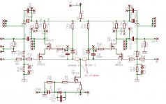
The problem seems to be due to different temperature reactions of the MOSFETs. I would try as attached and see the result. How do you call these source resistors with respect to their function . . . negative feedback . . . ? In addition, I would use one common heatsink for all MOSFETs (as I usually do).
Regards
Attachments
I don't think you would see such large variation with matched FETs, especially if the results are repeatable with different sets. Just my 2 cents.
BrianDonegan said:I don't think you would see such large variation with matched FETs, especially if the results are repeatable with different sets. Just my 2 cents.
You could be right.
He said: "It starts not too bad but slowly climbs till it rests at a too high number." I thought that the negative feedbacks might help.
My opinion is nothing more than a trial of trouble shooting.
Regards
In addition to the PSU diodes issue, another member here mentioed to me that there is an issue with one of the FET's is labeled backwards on the slikscreen. on Kari's boards.
Is this true?
Thank you,
-David
Is this true?
Thank you,
-David
I have thought about the following three possibilities:
[1] Mis-matching MOSFETs
[2] Different Vgs between Q4 and Q5
[3] Thermal effect
I removed [1] as he said all matched.
As long as the +/- inputs correctly refer to the 0V of the ground, [2] should be out as Q4 and 5 see the common Vs. To be sure of this, mpmarino could measure the Vgs of Q4 and 5 when the unbalanced Vd between Q4 and 5 is at maximum.
Based on my experience, the probability of bad cap is low. Maybe, I have been lucky.
Of course, there could be other reasons above my ability.
Regards
Thanks for all the consideration,
I had been through 2 sets of matched fets and then moved into unmatched fets out of the same tube. No difference, matched or unmatched. Same problem. VGS, regardless, is very close on the opposing fet in situ.
All fets were electrically isolated yet mounted to a 1/2" X 1" alu bar so thermally I should have been OK. When I removed the bar and cooled one sides worth of fets with compressed air I was able to temporary balance it out.
It does seem like some type of thermal issue as it 'creeps' bad then stabilizes bad. Or as was said maybe a bad cap? Maybe a hairline crack in a trace somewhere ??!?
Thanks guys...I won't have time to go back to this for a while so further troubleshooting probably won't happen anytime soon. I'm looking at a couple of other options right now. I will solve the mystery some day though! Too stubborn not to.
Member
Joined 2002
mpmarino said:Thanks for all the consideration,
I had been through 2 sets of matched fets and then moved into unmatched fets out of the same tube. No difference, matched or unmatched. Same problem. VGS, regardless, is very close on the opposing fet in situ.
All fets were electrically isolated yet mounted to a 1/2" X 1" alu bar so thermally I should have been OK. When I removed the bar and cooled one sides worth of fets with compressed air I was able to temporary balance it out.
It does seem like some type of thermal issue as it 'creeps' bad then stabilizes bad. Or as was said maybe a bad cap? Maybe a hairline crack in a trace somewhere ??!?
Thanks guys...I won't have time to go back to this for a while so further troubleshooting probably won't happen anytime soon. I'm looking at a couple of other options right now. I will solve the mystery some day though! Too stubborn not to.
I think you should just give up on that board and maybe ask for a new one. Ask russ i'm sure he has a new one to Donate. I think this will cure your problem I'm starting to think it is a missing trace or a none shorted one.
You have replaced ALL parts right ? The diodes were the cure for mine on the pre-amp.
Another suggestion change the pad's.. I did and that cured problems also.
An externally hosted image should be here but it was not working when we last tested it.
Well, I'ld like to donate 2 cents also, just because the description reminds me of 2 things... Thermal could be a problem, Yes. I also always use some kind of sink where the 2 opposing devices are 3mm apart or on opposite sides of the sink or something... But, you've heard that already...
How about this??? Many years ago, when I started debuging these things, I had a bad signal generator output connector. I spent many hours saying what the $%^&*. Eventually I realized what was happening. I would leave out the resistor at the input from the Gate to ground on my proto's. I expected my signal generator to have 50 ohm output impeadance so there is really no reason to have any resistance to ground on some circuits. But, there is. The capacitance at the gate will charge and float up and down however it likes if you dont pull it down with some very high resistance to ground, or somewhere. Whenever my signal generator went bad signal was lost but the inpuit node would start floating around... I see a 100K to ground there dont I??? Check that puppy out!!! Or maybe even the cascode Transistor
Just 2 more cents...
O.K. Just 2 more Cents... I think the source R's are reffered to as DeGeneration resistors...
flg said:
. . . reffered to as DeGeneration resistors . . .
Once I gave a question to this forum,
asking what is the "degeneration resistor."
And, have waited for an answer until now . . .
Thanks to flg, I got it. 🙂
For me, understanding meaning of words
is often as difficult as understanding technical things.
Regards
Yes, Great! Happy to help if I can... I don't really understand the association with the word degeneration but, they kill gain! They basically mess with the gate voltage to ground as the source current is changing. They will have the effect of linearizing the higher gain with more current, lower gain with less current, phenomena. It's value ussually is a compromise with the amount of gain we need and low distortion. They also help with balancing parallel transistors and preventing catastrophic failure during shorts...
I'm not sure if they are still called that in a JFET circuit though... The purpose there is to create a source more positive than the gate (or gate more negative than the source) to set bias current😉
I'm not sure if they are still called that in a JFET circuit though... The purpose there is to create a source more positive than the gate (or gate more negative than the source) to set bias current😉
Yeah . . .
I summed up and wrote down the degeneration resistors as usefull means. The lost gain could be compensated, if necessary, with increased sizes of the X-feedback resistors.
And, the degeneration resistors might also boost the SuSy effect.
Regards
I summed up and wrote down the degeneration resistors as usefull means. The lost gain could be compensated, if necessary, with increased sizes of the X-feedback resistors.
And, the degeneration resistors might also boost the SuSy effect.
Regards
Member
Joined 2002
Can any one suggest a Volume pot for about $150 us ish. It needs to be Balanced. I'm not going any where near the relay based ones.
Been running this in Single Ended Mode and sounds pretty detailed. Now to unleash balanced. 🙂
Been running this in Single Ended Mode and sounds pretty detailed. Now to unleash balanced. 🙂
Jase,
You can use what I have used ... ELECTROSWITCH 4-Deck 23 Position
Chris from partsconnexion has a preset series of resistors that go with this switch to create a very nice 10k balanced stereo attenuator. Total price is easily under CDN$150.
Cheers, Terry
You can use what I have used ... ELECTROSWITCH 4-Deck 23 Position
Chris from partsconnexion has a preset series of resistors that go with this switch to create a very nice 10k balanced stereo attenuator. Total price is easily under CDN$150.
Cheers, Terry
Member
Joined 2002
metalman said:Jase,
You can use what I have used ... ELECTROSWITCH 4-Deck 23 Position
Chris from partsconnexion has a preset series of resistors that go with this switch to create a very nice 10k balanced stereo attenuator. Total price is easily under CDN$150.
Cheers, Terry
I shal look into this now. Do you hear any tick's or pop's or any thing like that ?
jleaman said:Can any one suggest a Volume pot for about $150 us ish. It needs to be Balanced. I'm not going any where near the relay based ones.
Been running this in Single Ended Mode and sounds pretty detailed. Now to unleash balanced. 🙂
Why no relays?
Member
Joined 2002
After so many uses they just stop working I have had my relay based volume pot for less than a year and it is already failing 🙁
jleaman said:After so many uses they just stop working I have had my relay based volume pot for less than a year and it is already failing 🙁
That sounds like some very poor quality relays, or relays that are not designed for a lot of cycles.
The G6K and G6H I use have never given me any problems.
Member
Joined 2002
Russ White said:
That sounds like some very poor quality relays, or relays that are not designed for a lot of cycles.
The G6K and G6H I use have never given me any problems.
Oh yeah. I use MINE SO MUCH..
- Home
- Amplifiers
- Pass Labs
- My Take on X-BOSOZ