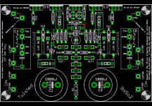
Very nice setup, Russ! Well, you cant have room enough😉 Somehow you allways work out short😉And here is how things fit inside
Steen🙂
that thing looks like a 2x50W amplifier.
The first amplifier I built looked smaller and had about that much capacitance.
looks Greeeeeeaaaatt !!!!
The first amplifier I built looked smaller and had about that much capacitance.
looks Greeeeeeaaaatt !!!!
steenoe said:Here is another one. My friend Magura (crazy soul) wanted to have a real listen to a Twisted preamp with some serious cans as supply bypass. That guy is just nuts😀 😀
Steen🙂
BTW Terry, could you please put some designations on your funky drawing?? I dont quite understand your setup, but initially it spells trouble to me!
Hi Steen,
I tried to do a better drawing. I will attach it here.
Basically what I'm thinking to do is to is to power one PSU board with one side of the 55-0-55 for the positive rail and one side of the 16-0-16, and powere the other board with the other side of the leg of the windings and share the venter tap. If it is better to just run parallel I will do that. I was trying to find a way to not have unused windings.
Hope that makes sense.
Blessings, Terry
Attachments
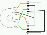
Hi Terry. I am not sure that arrangement will work. Each side of the centertap is in opposite phase, so its probably not safe to do 2 positive rails with the same common (gnd). I am not quite sure about this, though.
Any chance you could split the centertaps so you get 2 independant secondaries? Its doable sometimes, when the centertap is just soldered together.
You better ask this question over in the Power supply department. (If nobody else answers)
Steen🙂
Any chance you could split the centertaps so you get 2 independant secondaries? Its doable sometimes, when the centertap is just soldered together.
You better ask this question over in the Power supply department. (If nobody else answers)
Steen🙂
Question on R10/R11
I looks like R10 and R11 provide current to the two VREFs(REF1 and REF2). I am building a second pair of XBOSOZ (to try some things) and don't have any good 50K, closest I have in nice resistors is 47K. Is that ok? I am inclined to say it is as long as I keep the current to less than the 20ma max of the LM4040, am I correct? As it is that resistor is only allowing less than 2ma. So could I go as low as say 22K and maybe get a bit stiffer regulation in the bargain?
Cheers!
Russ
Second Question
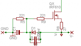
I am letting my ignorance hang out here, but can(or should) the value of the zener diode D1 change with the voltage of the negative rail? I want to figure out how much current is flowing through that beast, as I am wondering if it is getting warm with negative rail of 20V.
:EDIT: accrording to my calculations D1 (6.8V zener) should be passing about .8W from GND to V- via the 221 ohm resistor(R5). Would it be ok to increase the value of R5 to get that down to say .25W? So something like 680R? What would be the consequence of doing that? Also that means that that right now that 221 ohm resistor is doing a sight more than 1/4W right? I am almost thinking R5 should be like 680R - 1K. with a 20V rail.
Basically what I'm thinking to do is to is to power one PSU board with one side of the 55-0-55 for the positive rail and one side of the 16-0-16, and powere the other board with the other side of the leg of the windings and share the venter tap. If it is better to just run parallel I will do that. I was trying to find a way to not have unused windings.
Yes Terry, that's EXACTLY what I did. If you refer back half a dozen pages, you will see I am had some trouble but never explained to anyone that I was sharing the CT between two boards... (just too ********** stupid for this hobby!)
Here's the scenario... either board works fine. When BOTH are connected, hot zeners and resistors in the regulator area.
In short, I don't think it works... I will be testing it again shortly running off one secondary in parallel like your original setup.
Thanks to Steenoe for the HINT!
Is that transformer big enough for ya?
Russ... I may be a little bit slow, but are you having hot R & zener problems?
I bumped my 220's up to 1/2 watt based on this post from Eapavant...
http://www.diyaudio.com/forums/showthread.php?postid=850931#post850931
I bumped my 220's up to 1/2 watt based on this post from Eapavant...
http://www.diyaudio.com/forums/showthread.php?postid=850931#post850931
Hey man, your not any more slow than I am. 🙂 Actually the thing is working fine, but that part of the PCB is registering pretty warm with my IR thermometer, and I was trying to track down why. Now that I do the calcs I can see why. I think R5 either needs to be a .5 to 1W part or needs to be a higher value like 680R.
Looking at the CCS part of the circuit it looks to me that all that zener section does is provide a 6.8V voltage refernce to the gate of the QX FET. I Am wondering if it really needs 90ma(which it gets with 221R) or if 30ma is enough(which it would get with 680R).
Hi Guys,
OK, I've got a couple more questions. First of all I won't use both sides of the center tap. The PE tranny has plenty of amps to handle two boards just running them in parallel I'm sure.
So here's my question. Should I go ahead and change out R5 so I don't end up with a black spot on my boards?
Would it be better to go to a higher resistance or higher wattage?
Also, Does it matter which spade I attach the center taps to? AC+1 or AC+2, AC-1 or AC-2?
Thanks, Terry
OK, here's an update.
I hooked up the PSU to my transformer. Connected the two center taps to AC+2 and AC-2.
I don't have the MOSFETs soldered to the Twisted BOSOZ boards yet so I was only able to test the PSU bords so far. I used the two 33V zeners in the + side and one 15V zener in the - side. Filled the empty slots with jumpers.
I'm getting +75.3/-21.38VDC on the outputs. Nothing is warm at all. I suppose I will have to have a load on it to see the over-heating problems.
Anyway, do those voltages look about right?
Thanks, Terry
still4given said:
Anyway, do those voltages look about right?
Thanks, Terry
Yes, unloaded those look good. 🙂
For now I would try a 680 or 1K 1/4W resistor for R5 on the preamp. either that or use a 1W 221R.
I think it will work fine that way.
Hi Russ,
Thanks for the advise. I've got one small problem. Now that I have the boards stuffed, I can't tell which one is R5. Is there a pic of the screen somewhere so I can print it out. Probably be handy again sometime.
Blessings, Terry
Thanks for the advise. I've got one small problem. Now that I have the boards stuffed, I can't tell which one is R5. Is there a pic of the screen somewhere so I can print it out. Probably be handy again sometime.
Blessings, Terry
Learning experience
Ok so I went way back and looked at the schematic I started from (which was based on Metalman's layout plus some mods from Kari)
http://www.diyaudio.com/forums/attachment.php?s=&postid=713646
And then I went and compared it to the schematic which I found later from Terry Aben himself:
http://www.diyaudio.com/forums/attachment.php?s=&postid=562625&stamp=1106940440
Well look at R18 in Terry's Schematic, it is equivalent to R5 in mine. Well his is 10K!!!
The gate of the FET really only cares about voltage, not current. So I think and R5 of 1K is fine, and who knows maybe even 10K???
Any input is welcome.
:edit: for completeness here is my first schematic:
http://www.diyaudio.com/forums/attachment.php?s=&postid=761059&stamp=1131374698
Re: Learning experience
Maybe I should wait until you guys sort this out before I swap out R5. 😀
Blessings, Terry
Russ White said:Ok so I went way back and looked at the schematic I started from (which was based on Metalman's layout plus some mods from Kari)
http://www.diyaudio.com/forums/attachment.php?s=&postid=713646
And then I went and compared it to the schematic which I found later from Terry Aben himself:
http://www.diyaudio.com/forums/attachment.php?s=&postid=562625&stamp=1106940440
Well look at R18 in Terry's Schematic, it is equivalent to R5 in mine. Well his is 10K!!!
The gate of the Fet really only care about voltage. So I think and R5 of 1K is fine, and who knows maybe even 10K???
Any input is welcome.
Maybe I should wait until you guys sort this out before I swap out R5. 😀
Blessings, Terry
I will send out new R5 resistors to anyone who wants them, and change future kits accordingly, after we settle on a final value.
- Home
- Amplifiers
- Pass Labs
- My Take on X-BOSOZ