Hi Promitheous,
Biran is working on getting the Darwin order deatils completed, so it won't be long now till its up. Just a day or so I imagine. I would go ahead and order after he is finished with that since you want both the Joshua Tree and the Darwin.
Thanks for all the input and ideas too! Very helpful.
Cheers!
Russ
Hi Russ. Really good job🙂 Are you planning on a nice display and Remote controlJoshua Tree and the Darwin.
option for those relayboards. That would be really cool.
Imagine a Twisted BosoZ with remote control and displaying the volume and the selected input. 😎
Steen🙂
steenoe said:Hi Russ. Really good job🙂 Are you planning on a nice display and Remote control
option for those relayboards. That would be really cool.
Imagine a Twisted BosoZ with remote control and displaying the volume and the selected input. 😎
Steen🙂
Eventually the plan is a "master" controller which can control Darwin, Joshua Tree, and Kookaburra. But it is a little ways off as Brian and I have a lot of catching up to do, and families too! 😀
Steen have to hand it to you, you were dead on right about this preamp. It sounds simply wonderful.

Cheers!
Russ
Sounds good to me allright😀 I just went daydreaming again😉Eventually the plan is a "master" controller which can control Darwin, Joshua Tree, and Kookaburra. But it is a little ways off as Brian and I have a lot of catching up to do, and families too!
I am not in a hurry, as some of you might think😀
Steen 🙂
BTW, the Twisted sounds pretty good allright🙂 Mighty fine job.
metalman said:Have you tried it balanced yet? If not, you haven't heard it at its best!
Unfortunately no 🙁( But hopefull I will have a prototype of your SuSy chipamp done here soon. 😀 Then I will be all smiles.
Terry, one question for you if you don't mind. What would be the effect of changing the value of R1,R2,R6, and R7 and are they tied to the bias current set by R8.
Thanks!
Russ
Replacement R5's
I just sent out the first batch of replacement R5 resistors (10K) to the US customers who purchased kits or just the Dale resistor pack. I'll send to international customers tomorrow.
If you got Dales, I am sending Dale replacements.
If you live in the US and don't have them by this time next week, send me an email and I'll be sure you get them.
Originally posted by Russ White
What would be the effect of changing the value of R1,R2,R6, and R7 and are they tied to the bias current set by R8.
Ideally the values of R1,R2, R6, R7 are tied to the bias current, chosen so that the voltage across R1 etc. is approximately the same as the voltage across Q3 + Q5. However, there is quite a bit of lattitude in how close that needs to be matched, and it only really affects the maximum output swing capability wihtin certain limits. The limits being to keep a minimum of 20V across Q3 + Q5. Dropping below that value seems to start taking away some of the clarity.
A last tidbit. Using a balanced output, there is NO hiss or noise even with the volume at full output. Sweet dead silence!
metalman said:A last tidbit. Using a balanced output, there is NO hiss or noise even with the volume at full output. Sweet dead silence!
Ok, Chippy SuSy can't get done soon enough now. 🙂
Hi Russ,
Will the "Joshua Tree Balanced Complete Kit " come with everything I will need except for the transformer?
Thanks, Terry
Will the "Joshua Tree Balanced Complete Kit " come with everything I will need except for the transformer?
Thanks, Terry
Yes. That's how we like to do it. We even sell a trafo for it 😉
It will have all the hardware, just like the x-bosoz kit does, and even the ribbon cable to connect controller to relay board, connectors and crimp pins.
It will have all the hardware, just like the x-bosoz kit does, and even the ribbon cable to connect controller to relay board, connectors and crimp pins.
Hi Terry. Yes In balanced out, it really performes! I have no balanced input for the Twisted(sad enough) but I do have an amp with balanced input so I have the pleasure of listening to the Twisted in full bloom, I guess.Have you tried it balanced yet? If not, you haven't heard it at its best!
It really sounds great, at least to my ears🙂 I havent heard any thing better at this point!!
Steen😎
steenoe said:
It really sounds great, at least to my ears🙂 I havent heard any thing better at this point!!
Steen😎
and -one of these days-you'll try some nice interstage xformer,driven with toob,and you'll say-"man,this is the magic!"

OK Folks, I am going to show my ignorance here and beg for mercy. Someone please help me figure this out. 🙂
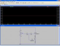
I want to be able to calaculate the bias current out of the CCS and know how much power is being dissipated by R8 in my schematic.
If I am aiming for a bias of 80-100ma from the CCS (40-50ma per side) what value/rating should R8 be if R1, R2, R6, R7 are 1.5K.
Supply rails are +75V and -20V
The circuit function fine and sounds great with a R8 values of 27R but according to my calculations that means its dissipating 14W!!!! that can't be possible now can it?
Also note that R5 is now 10K.
I am stumped. Someone please help me understand.
You can find my schematic here:
http://www.diyaudio.com/forums/showthread.php?postid=855588#post855588
I want to be able to calaculate the bias current out of the CCS and know how much power is being dissipated by R8 in my schematic.
If I am aiming for a bias of 80-100ma from the CCS (40-50ma per side) what value/rating should R8 be if R1, R2, R6, R7 are 1.5K.
Supply rails are +75V and -20V
The circuit function fine and sounds great with a R8 values of 27R but according to my calculations that means its dissipating 14W!!!!
that can't be possible now can it?Also note that R5 is now 10K.
I am stumped. Someone please help me understand.
You can find my schematic here:
http://www.diyaudio.com/forums/showthread.php?postid=855588#post855588
V(R8) = V(D1) - Vgs where Vgs for the IRF610 = 4 to 4.5V typically
then
I(R8) = V(R8) / 27ohm
Assuming that the Vgs = 4V and the zener diode D1 is 9.1V, then
V(R8) = 9.1 - 4 = 5.1V
then
I(R8) = 5.1V / 27ohms = 0.189 A or 189mA
The power dissipation on R8 is then
P = I*I*R = 0.189A * 0.189A * 27ohm = 0.963 W
The entire circuit should only dissipate about 10W per channel.
Hope this helps.
Terry
then
I(R8) = V(R8) / 27ohm
Assuming that the Vgs = 4V and the zener diode D1 is 9.1V, then
V(R8) = 9.1 - 4 = 5.1V
then
I(R8) = 5.1V / 27ohms = 0.189 A or 189mA
The power dissipation on R8 is then
P = I*I*R = 0.189A * 0.189A * 27ohm = 0.963 W
The entire circuit should only dissipate about 10W per channel.
Hope this helps.
Terry
The spice model looks more or less correct, except that it will grossly overestimate the power dissipation of the FET. One problem might be that you have substituted a different FET in the model. You can download an exact spice model for the IRF610 from International Rectifiers website.
 Cheers!
One more question, It appears to me that the output impedance of the circuit would be 750ohms. Am I on the right track?
- Home
- Amplifiers
- Pass Labs
- My Take on X-BOSOZ