Here is yet another version of this great classic, the Twin Tee rejector.
No rocket science involved, it is basically a plain vanilla bridged T filter, followed by a correction network, very much like the B & K 1607:
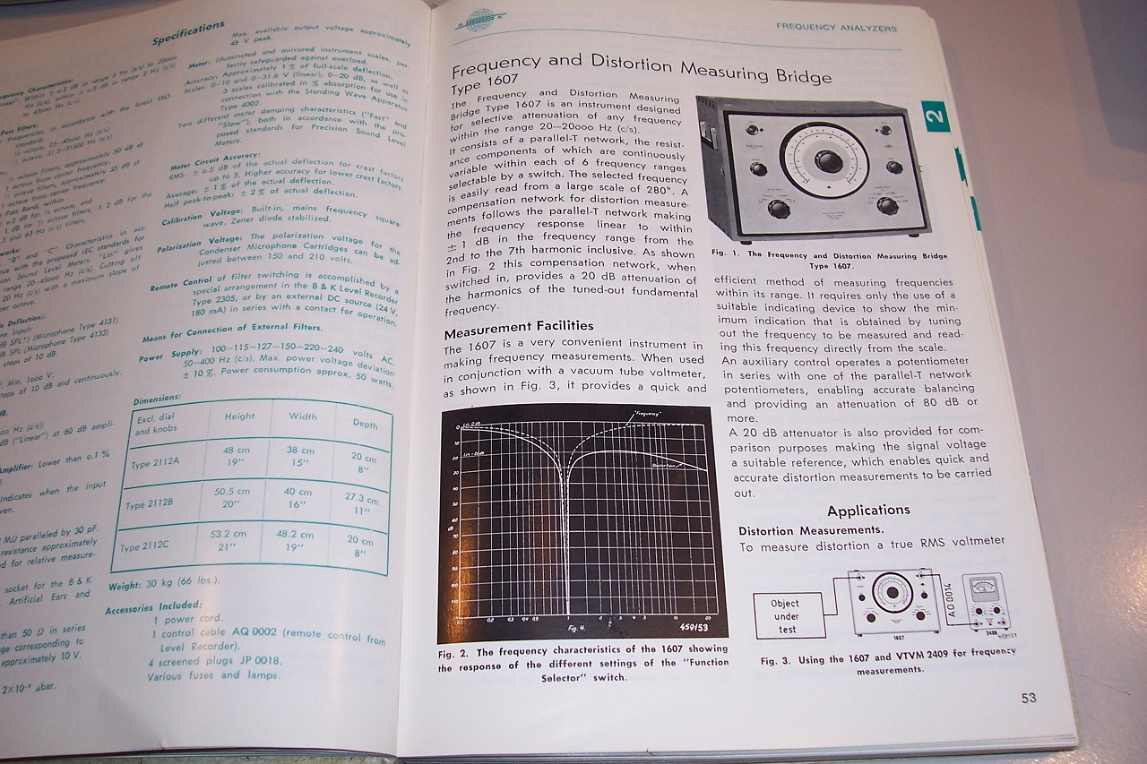
-Except for two things- : I didn't make it variable, or even adjustable, because of the huge complications involved, and the equalization is rather smarter than the B & K's.
The 1607 does it through the lowest common denominator, knocking off 20dB at all harmonic frequencies, which is the easiest path, and was understandable in the '60s context, where THD levels below 0.1% were an exception, but nowadays, with THD figures below the ppm being commonplace, such a simplification is no more possible: when the distortion residues already sit at the µV level or below, drowning them into noise by twenty additional dB's is completely unacceptable.
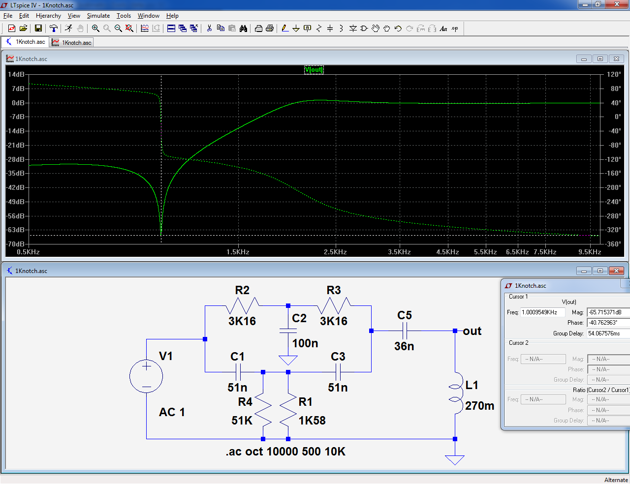
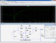
The correction network I devised uses a LC filter to lift the response around the second and third harmonics, resulting in a response of 0dB, +/-0.5dB, which is convenient and effective.
There is a slight hump at 2.3kHz, but the second and third keep well inside the +/-0.5dB envelope.
An additional benefit of this network is high-pass filtering, helping in removing hum residues.
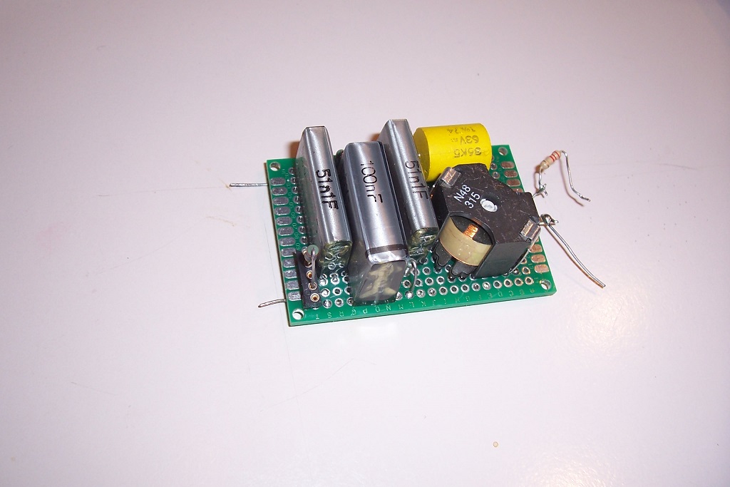
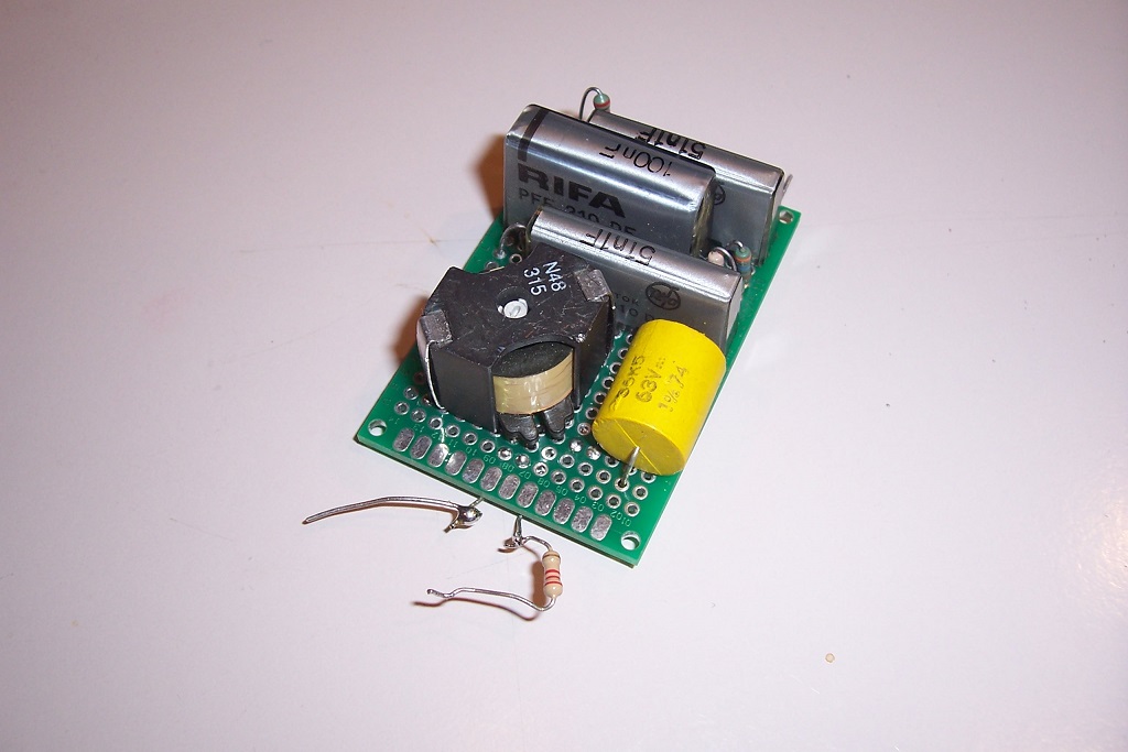
The ferrite core inductor might raise eyebrows, since cored inductors introduce distortion of their own of typically 0.01%, but here, the inductor is subjected mainly to harmonics, and the worst it can do is introduce various minor intermodulations products, which are not numerically significant.
I voluntarily blunted the notch to a convenient -60dB (the sim shows -65dB because some of the losses are unaccounted for) by tweaking the resistors value, since the residue is meant to be fed into a conventional THD analyzer.
Of course, there is a small price to paid for the improvement: the source impedance must be low, preferably below 100 ohm, and the analyzer's impedance should be high, preferably 1Megohm or higher, but none of this poses a problem with semiconductor gear.
Note that thanks to the parasitics (the inductor's parallel capacitance, mainly), the real life response is even better than the simulated one.
No rocket science involved, it is basically a plain vanilla bridged T filter, followed by a correction network, very much like the B & K 1607:
-Except for two things- : I didn't make it variable, or even adjustable, because of the huge complications involved, and the equalization is rather smarter than the B & K's.
The 1607 does it through the lowest common denominator, knocking off 20dB at all harmonic frequencies, which is the easiest path, and was understandable in the '60s context, where THD levels below 0.1% were an exception, but nowadays, with THD figures below the ppm being commonplace, such a simplification is no more possible: when the distortion residues already sit at the µV level or below, drowning them into noise by twenty additional dB's is completely unacceptable.
The correction network I devised uses a LC filter to lift the response around the second and third harmonics, resulting in a response of 0dB, +/-0.5dB, which is convenient and effective.
There is a slight hump at 2.3kHz, but the second and third keep well inside the +/-0.5dB envelope.
An additional benefit of this network is high-pass filtering, helping in removing hum residues.
The ferrite core inductor might raise eyebrows, since cored inductors introduce distortion of their own of typically 0.01%, but here, the inductor is subjected mainly to harmonics, and the worst it can do is introduce various minor intermodulations products, which are not numerically significant.
I voluntarily blunted the notch to a convenient -60dB (the sim shows -65dB because some of the losses are unaccounted for) by tweaking the resistors value, since the residue is meant to be fed into a conventional THD analyzer.
Of course, there is a small price to paid for the improvement: the source impedance must be low, preferably below 100 ohm, and the analyzer's impedance should be high, preferably 1Megohm or higher, but none of this poses a problem with semiconductor gear.
Note that thanks to the parasitics (the inductor's parallel capacitance, mainly), the real life response is even better than the simulated one.
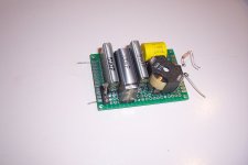
Attachments


Elvee,
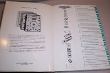
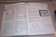
What book or flier is that? Can you take a pic or two of the following pages?
Good job and I liked the design for the humble tool also.
Cheers,
What book or flier is that? Can you take a pic or two of the following pages?
Good job and I liked the design for the humble tool also.
Cheers,

BTW, does someone remember an article about a variant of the notch filter, I think the author named it "canyon filter" or something similar, because the maximum attenuation was not a single point, but a range of frequency of a few Hz.
The intention was to make the exact tuning of such a filter much less critical.
I think I saw it in Electronics & W.W., but it could also be EDN, Electronic Design, or another one....
The intention was to make the exact tuning of such a filter much less critical.
I think I saw it in Electronics & W.W., but it could also be EDN, Electronic Design, or another one....
- Status
- Not open for further replies.