The ZEN amplifier by Nelson Pass is no doubt a real milestone in the amplifier world.
It is dead simple but good.
But it has got 3 issues:
1. Low input impedance.
2. Low gain.
Both of these issues are fixed by using Bride Of Zen, BOZ.
3. Somewhat high THD distortion.
Now this is no issue for Mr Pass - he is not bothered,
because his amplifiers sounds good no matter what.
My Take on the original Zen also fixes those 3 issues.
The price to pay is the addition of one input transistor.
I will later post a full circuit of my Zen style amplifier.
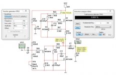
To begin with have a look at the simplified schematic.
It is dead simple but good.
But it has got 3 issues:
1. Low input impedance.
2. Low gain.
Both of these issues are fixed by using Bride Of Zen, BOZ.
3. Somewhat high THD distortion.
Now this is no issue for Mr Pass - he is not bothered,
because his amplifiers sounds good no matter what.
My Take on the original Zen also fixes those 3 issues.
The price to pay is the addition of one input transistor.
I will later post a full circuit of my Zen style amplifier.
To begin with have a look at the simplified schematic.
Attachments


F8, anyone?
https://www.diyaudio.com/community/threads/first-watt-f8.358672/post-6654823
But then IRF9610 is much cheaper than 2SJ74.
And you can argue how much the extra input / output coupling caps costs.
Patrick
Looks like an interesting version.
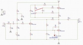
I knocked out a quick single channel layout, 70x50mm:


I was lazy and just did a ground plane with a notch to roughly separate the input / power sides.
The IRF9610 appears to only dissipate ~20mW, so I figured it would be fine for board mount.
The power traces are 2mm or 80mil, which should be enough, but I might try to fatten them up where the space permits.
Will be interesting to see how this one sounds 🙂
I knocked out a quick single channel layout, 70x50mm:
I was lazy and just did a ground plane with a notch to roughly separate the input / power sides.
The IRF9610 appears to only dissipate ~20mW, so I figured it would be fine for board mount.
The power traces are 2mm or 80mil, which should be enough, but I might try to fatten them up where the space permits.
Will be interesting to see how this one sounds 🙂

Looking at the original Zen, there is a 9.1v Zener across Q1 G-S to protect from transients:

Is this required for this version also?
Z1 is essential to insure that an input transient cannot exceed the 20 V gate rating of the Mosfet.
Is this required for this version also?
Finally fired this one up (literally..)
Applied 36v from a 5A supply with 8 ohm load.
Curiously, R9 contained smoke..
Dissipation of R9 and R12 was supposed to be 1.6W, so I used 3W.
I must have done something wrong but I just can't see what it is. Any ideas?

Edit: I've missed the connection between R7 and R5:Q4, although the sim shows that no current will flow through Q1/Q2 in that case which is obviously not what I found.
Applied 36v from a 5A supply with 8 ohm load.
Curiously, R9 contained smoke..
Dissipation of R9 and R12 was supposed to be 1.6W, so I used 3W.
I must have done something wrong but I just can't see what it is. Any ideas?
Edit: I've missed the connection between R7 and R5:Q4, although the sim shows that no current will flow through Q1/Q2 in that case which is obviously not what I found.
36V * 2.27A ~ 82W. ~41W for each IRF540, needs extra care in heatsink selection due to higher RϴJC
I have large heatsinks attached (300x200x50mm) to help dissipate the heat and ensured that there was no continuity between the heatsink and the mosfets.
R9 lasted <5s before the column of smoke appeared.
I made the R7 - R5:Q4 connection on the second board and the DBT lit up same as the first board.
R9 lasted <5s before the column of smoke appeared.
I made the R7 - R5:Q4 connection on the second board and the DBT lit up same as the first board.
Yep, took care of that already but that wasn't the issue.Edit: I've missed the connection between R7 and R5:Q4, although the sim shows that no current will flow through Q1/Q2 in that case which is obviously not what I found.
The gate of Q1 does not have a DC path, check the original schematics, there is a mistake there.
What anibal said:
Attachments
I already fixed that connection (post 10, 12 & 15).What anibal sai
The irf540 looked to be suitable up to ID=28A and PD=150W:
What would be a suitable alternative?
eeenyweeeny TO220 case with Iq 2A+ and 18V across , no way!!
IRFP240, IRFP150
IRFP240, IRFP150
R100’seeenyweeeny TO220 case with Iq 2A+ and 18V across , no way!!
IRFP240, IRFP150

- Home
- Amplifiers
- Pass Labs
- My Take on the original ZEN - An attempt to improve things.