Re: JLH Shunt
AndrewT
This was in ETI in 1981? i think, SandtK can confirm on date.
I have previously search the forum looking for some reference to this circuit, without luck.
SandyK sent it to me a while ago,,,,, thanks again SandyK.
I have used the superreg's (in some form or another) for clocks and other limited current stuff and they work well.
I've tried the JLH in preamps, input stage of amps, cd buffer psu etc, It is very good.
Can anyone or has anyone seen a reference to it? (besides SandyK, a few weeks ago)
I wonder if it has been overlooked or dismissed for some reason.
and why, (might save me from the same mistakes)
SandyK
what year was the article?
allan
AndrewT said:The JLH shunt was posted in the last two weeks, but I can't remember where or in what context.
AndrewT
This was in ETI in 1981? i think, SandtK can confirm on date.
I have previously search the forum looking for some reference to this circuit, without luck.
SandyK sent it to me a while ago,,,,, thanks again SandyK.
I have used the superreg's (in some form or another) for clocks and other limited current stuff and they work well.
I've tried the JLH in preamps, input stage of amps, cd buffer psu etc, It is very good.
Can anyone or has anyone seen a reference to it? (besides SandyK, a few weeks ago)
I wonder if it has been overlooked or dismissed for some reason.
and why, (might save me from the same mistakes)
sandyK said:I have previously mentioned the effectiveness of the JLH shunt in various threads.
If anybody would like to see the original ETI article, send me an email.
SandyK
SandyK
what year was the article?
allan
Attachments
JLH regulator
Allan
The year of publication is not known. The clipped out pages from my original copy of ETI, show page numbers only.
Perhaps the JLH website now has this information ?
SandyK
Allan
The year of publication is not known. The clipped out pages from my original copy of ETI, show page numbers only.
Perhaps the JLH website now has this information ?
SandyK
Are you planning on building any prototype for both regulators?
I might be curious on how to adapt any of your circuits, particularly the super-regulator, for a power amp. Both for low and high current stages.
I might be curious on how to adapt any of your circuits, particularly the super-regulator, for a power amp. Both for low and high current stages.
JLH regulator
Carlmart
awpagan (Allan) , myself, and vhfman (David) have all been using the basic design with excellent results in Class A preamplifiers
(15-20 volt +- supply rails at >100mA per channel bias.
I am using + and - JLHs for the front end of my 15W Ch. Class A Silicon Chip amplifier. Allan has adapted the circuit to work with
+ and - 55V rails supplying the front end of a Silicon Chip 100W/Ch ULD amplifier, with excellent results, even after already using the original design's regulated front end supply. This design gives a marked improvement over the noise performance of conventional voltage regulators ,with VERY low impedance past 100KHZ. The use of the JLH design results in improved ambience retrieval, better detail,an improved soundstage, as well as a more neutral sound.
SandyK
Cauhtemoc said:Attached is a simulation comparing the performance of various regulators. Green is an LM317, blue is an LT1085, red is the POOGE regulator found on ALW's website (here), cyan is my POOGE regulator, pink is the Sulzer regulator (with NE5534), dark green is the latest version of Walt Jung's super regulator (with preregulator and AD825), and orange is my super regulator.
Note that my POOGE regulator outperforms the Sulzer regulator and even rivals the Jung regulator at higher frequencies. Because of the low cost you can easily run two of them in series, this would lower the noise floor to below -200 dB. My super regulator performs around 60 dB better than my POOGE regulator, and running two of them in series would lower the noise floor to well below -300 dB.
Note that they are only simulations however, and as such they should be taken with a grain of salt. If anyone wants to build these be my guest.
What about the other specs, compared to the other regulators, like impedance?
Re: JLH regulator
Well, I mean application for Cauhtemoc's design, not JLH's. Or am I misinterpreting your comments?
When you say you used the basic design you mean Cauhtemoc's Reg1?
sandyK said:Carlmart
awpagan (Allan) , myself, and vhfman (David) have all been using the basic design with excellent results in Class A preamplifiers
(15-20 volt +- supply rails at >100mA per channel bias.
I am using + and - JLHs for the front end of my 15W Ch. Class A Silicon Chip amplifier. Allan has adapted the circuit to work with
+ and - 55V rails supplying the front end of a Silicon Chip 100W/Ch ULD amplifier, with excellent results, even after already using the original design's regulated front end supply. This design gives a marked improvement over the noise performance of conventional voltage regulators ,with VERY low impedance past 100KHZ. The use of the JLH design results in improved ambience retrieval, better detail,an improved soundstage, as well as a more neutral sound.
SandyK
Well, I mean application for Cauhtemoc's design, not JLH's. Or am I misinterpreting your comments?
When you say you used the basic design you mean Cauhtemoc's Reg1?
What about the other specs, compared to the other regulators, like impedance?
Simulating the impedance or noise figure is very hard, these have to be measured. I will do this once I have built the prototypes.
Hi
The Sigma22 reg circuit looks like similar to the descrete regulator I used in the "ugly amp" circuit I made a while ago, except it was for only 50mA or so with a smaller pass transistor. I cascode the differential though. http://www.diyaudio.com/forums/attachment.php?postid=1121942&stamp=1170317002 Still works BTW🙂
If simplicity is the goal, this is a regulator I used once in a small line amp.
Attachments
Simplicity
Maybe we have different ideas of what simplicity is. For me it means as few components as possible.
It was my mistake to perceive your design as having few simple parts... but it was only for one polarity. If I add the parts for V+ and V-, then we will have even more parts than the Sigma, which I think has too many.
In that sense, both the Sulzer and Jung's super-regulator have the advantage. Pity they only work on lower voltages and on higher current.
In that sense, I think that for high current/high voltage regulators I would prefer Kit Ryan's and Boak/Jung's, both published in "The Audio Amateur" years ago.
CBS240 said:If simplicity is the goal, this is a regulator I used once in a small line amp.
Maybe we have different ideas of what simplicity is. For me it means as few components as possible.
It was my mistake to perceive your design as having few simple parts... but it was only for one polarity. If I add the parts for V+ and V-, then we will have even more parts than the Sigma, which I think has too many.
In that sense, both the Sulzer and Jung's super-regulator have the advantage. Pity they only work on lower voltages and on higher current.
In that sense, I think that for high current/high voltage regulators I would prefer Kit Ryan's and Boak/Jung's, both published in "The Audio Amateur" years ago.
carlmart said:
Maybe we have different ideas of what simplicity is. For me it means as few components as possible.
It was my mistake to perceive your design as having few simple parts... but it was only for one polarity. If I add the parts for V+ and V-, then we will have even more parts than the Sigma, which I think has too many.
If you are referring to the j-fet reg circuit, there would be 6 transistors for + & -, only one p-channel j-fet required for the negative side, as the CCS can be n-channel for both sides. It was made to drive an OP-AMP IC. If you think that this is too many transistors, you would flip out to see the last amp circuit I made.😀
A differential has more gain for the error amp, acting kinda like a comparator. IMHO, you can't go wrong with cascode, small signal transistors are cheap. IMO, a good regulator should have a wide bandwidth in order to have good load rejection at higher frequencies. It is, essentially, an amplifier, for both DC and AC. If the circuit is driving a VAS or output in a typical class AB amp, it has to output a changing current for half the waveform and would have some higher order frequencies involved, if it is to maintain a 'perfect' non-fluctuating DC rail voltage. Take a look at the good ol' 723 IC. It too has a differential error amp.
http://www.datasheetarchive.com/pdf/3509737.pdf
Oh, I am certainly aware of how many parts are inside any IC.
So let me be honest. When I mean simplicity it's actually meaning how many parts I have to solder in to assemble it all.
If all the discrete parts came in a single chip for a quality regulator, I wouldn't mind the parts quantity.
That doesn't mean it doesn't have to fulfill high quality parameters. It certainly has.
For the purpose of understanding how the circuit works, discrete is the way to go because you can change the circuit components easily to experiment. Otherwise, using IC's where possible is obviously easier to implement, hence their creation in the first place. I agree with you on that. I'm using IC regulators for the new amp circuit I've been playing with for that very reason.🙂 The 'ugly amp' I made is purely experimental, and the complexity there is of little issue to me since it is the only one I made.
Re: JLH regulator
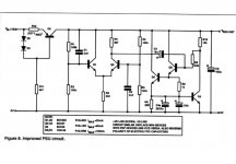
This nifty little circuit consists of a ripple detector, a constant current source and a shunt regulator. It's intended as a piggyback for a standard three pin reg like LM317 to clean up its output. It's capable of handling currents from mA to several A without major modification.
Parts are expected next week. Thanks for the input and greetings to you guys downunder!😎
sandyK said:... excellent results, even after already using the original design's regulated front end supply.
This design gives a marked improvement over the noise performance of conventional voltage regulators, with VERY low impedance past 100KHZ ...SandyK
This nifty little circuit consists of a ripple detector, a constant current source and a shunt regulator. It's intended as a piggyback for a standard three pin reg like LM317 to clean up its output. It's capable of handling currents from mA to several A without major modification.
Parts are expected next week. Thanks for the input and greetings to you guys downunder!😎
Re: Re: JLH regulator
Did you forget to attach the nifty little circuit?...
disco said:This nifty little circuit consists of a ripple detector, a constant current source and a shunt regulator.
Did you forget to attach the nifty little circuit?...
Re: Re: Re: JLH regulator
partslist
R1 100K
R2 100K
R3 2K2
R4 2K7
R5 100K
R6 100K
R7 33
R8 120K
R9 1K
R10 10K
R11 4K7
R12 20mA=33, 60mA=10, 100mA=6R8
C1 2u2
C2 2u2
C3 10u
C4a 2200u
C4b 2200u
C5 100u
Q1 BC549C
Q2 BC549C
Q3 BC637
Q4 BC637
Q5 BC637
Q6 BC636
D2 1N4148
D3 IN4148
According to http://www.tcaas.btinternet.co.uk/jlharticles.htm the article is published in Electronics Today International in 1994.
It's in post #8Originally posted by carlmart Did you forget to attach the nifty little circuit?...
partslist
R1 100K
R2 100K
R3 2K2
R4 2K7
R5 100K
R6 100K
R7 33
R8 120K
R9 1K
R10 10K
R11 4K7
R12 20mA=33, 60mA=10, 100mA=6R8
C1 2u2
C2 2u2
C3 10u
C4a 2200u
C4b 2200u
C5 100u
Q1 BC549C
Q2 BC549C
Q3 BC637
Q4 BC637
Q5 BC637
Q6 BC636
D2 1N4148
D3 IN4148
According to http://www.tcaas.btinternet.co.uk/jlharticles.htm the article is published in Electronics Today International in 1994.
Hmm … impressive simulated performance. Though I have a couple of suggestions to simplify the design:Cauhtemoc said:The second regulator is a cross between the POOGE and Walt Jung's super regulator. I use two transistors as a reference here as well, but I replaced the op amp with discrete components. I did not know how this would affect the performance, I mainly did this to lower the cost. The entire regulator can now be built for around $5.
1) Re-arrange the reference voltage from ground to output rail – this allows setting the current for the difference amp with a single resistor, and without the current being dependent on output voltage, and
2) Substitute the remaining current sources for J-FETs and resistors.
Attached is a drawing of the modified regulator. To complicate matters I have added a fold-back current-limiter.
KJ
Attachments

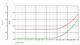
The red line in the graph is ripple rejection for 5.4V output in to 100 ohm, reference to the db-scale (frequency sweep of 1 volt AC in the input). The ripple rejection is at about –170 dB up to 4K Hz. The green line is load regulation for 5.4V output loaded with 100 mA DC and 100 mA AC, reference to the VOUT/V-scale, modulated ACV is at about 15 nV up to about 5K Hz. This equates to a dynamic output impedance of 150n Ohm, and which is bound to be ruined in any practical implementation.KJ42 said:
Hmm … impressive simulated performance. Though I have a couple of suggestions to simplify the design:
1) Re-arrange the reference voltage from ground to output rail – this allows setting the current for the difference amp with a single resistor, and without the current being dependent on output voltage, and
2) Substitute the remaining current sources for J-FETs and resistors.
Attached is a drawing of the modified regulator. To complicate matters I have added a fold-back current-limiter.
KJ
I think I’ll scrap my previous experiments in this area.
KJ
Attachments
Hmm … impressive simulated performance. Though I have a couple of suggestions to simplify the design:Cauhtemoc said:The second regulator is a cross between the POOGE and Walt Jung's super regulator. I use two transistors as a reference here as well, but I replaced the op amp with discrete components. I did not know how this would affect the performance, I mainly did this to lower the cost. The entire regulator can now be built for around $5.
1) Re-arrange the reference voltage from ground to output rail – this allows setting the current for the difference amp with a single resistor, and without the current being dependent on output voltage, and
2) Substitute the remaining current sources for J-FETs and resistors.
Attached is a drawing of the modified regulator. To complicate matters I have added a fold-back current-limiter.
KJ
KJ42 said:
Hmm … impressive simulated performance. Though I have a couple of suggestions to simplify the design:
1) Re-arrange the reference voltage from ground to output rail – this allows setting the current for the difference amp with a single resistor, and without the current being dependent on output voltage, and
2) Substitute the remaining current sources for J-FETs and resistors.
Attached is a drawing of the modified regulator. To complicate matters I have added a fold-back current-limiter.
KJ
I had thought about something like that myself, although I prefer to use BJTs over JFETs. I expect the design to change quite quite a bit once I have a prototype to experiment with, there are certainly a few things that can be improved.
- Status
- Not open for further replies.
- Home
- Amplifiers
- Solid State
- My take on regulators