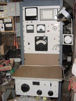
After my valve amp I decide to build a valve tester no doubt this type of thread as been posted many times. i wanted to build a tester that used standard components and was not the size of a suitcase so here it is
Spec
Anode 10-300V DC 100 ma limited
Screen 10-300V DC 30 ma limited
Heater supply 1.2- 22v DC 1.5A
Grid supply 0 / -30V
Anode currant measurement range 10 - 50 - 100 Ma meter
ma/v 0-20 or 0-5
Heater continuity LED
Heater Cathode insulation LED
Leak Short LED
Gas test push button
Patch panel to set valve base connections
home made case
i will not say i designed this tester just put it together after studying other tester (RAT , Sussex , AVO etc)
Nice neat wiring job for sure. Below are a pair of testers for the big ones. First is a class A tester for inputs of up to 1500 watts. The schematic. And a 2500V one shot pulse tester for most anything else up to the limit of the filament supply which is 12 Volts at 200 amps.
Attachments

Great job! Congrats!
Do you hace a schematic or more info, i like to build a similar one someday.
Do you hace a schematic or more info, i like to build a similar one someday.
Hi
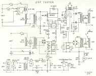
i have added a zip file with the info i used to build the tester and drawings etc. the heater supply was built using a kit of parts from china (ebay) less expensive than buying the components i uprated the diodes on the bridge rectifier and did not use the small heat sink supplied. the rest was built using perf board (not stripboard)
the meters all started life as 0-30V one used as standard (heater & Grid Volts) one was modified to 0-300V ( anode & Screen volts) one to 0.5V with shunts (anode currant) one to 200mv (ma/v). the scales where redraw with meter basic an excellent program
the millivoltmeter op amp circuit can from a post for the RAT tester Can not recall the posters name and was slightly modified to work with a 20 mv AC input. The HT transformer was a standard industrial isolation transformer 230V -230V 50VA. if you have a transformer with a secondary of 300V with a few tweaks you could build a tester with a output of 400V DC. all voltages are totally adjustable. you could of course use digital meters this would save you building the op amp AC millivoltmeter and even calibrated dials for the voltage adjustments
and for a simple tester the ma/v and continuity leds etc. could be easily omitted from a build
regards
Attachments
Are you still active on this forum? I would like to build your design, if I may. Can you repost those pictures please?
Hi I have found the photos still exist On this forum. If you select Gallery from the top menu.Then member gallery And look under keveas you will find the photos. Let me know if you find the photos and thanks for the interest
Regards
Regards
Hi Where the photos of any help ? If you need any more assistance let me know I put a lot of effort and time into my tester To test valves you simple use the AVO valve tester data book
I have seen info for sale on building a tester on eBay it’s years out Of date useing multitape transformers and high power wire wound Potentiometers but people seem to keep buying it
I did think of casing the drawings and putting them on eBay
You can use my drawings to make a simpler tester if need be By omting some of the functions
Your design looks very good. I am also looking at this design, but did not decide yet which one to make.
Tube Tester
Tube Tester
Last edited:
I also looked at that tester before I built mine
The original version anyway not sure what modifications have
Been made to it in the link posted
But decided against it because of the lack of voltage adjustment
I looked at a lot valve testers diy and commercial
A lot of them are emission testers only and unless your valve is
In there data book you have no test figures
I decided that the most logical testers where built by AVO
With adjustable voltages you can use the AVO data or even the valve data
Sheet to perform tests
You could make a tester along the lines of the one on your link
But useing the anode and screen supply’s from my drawing
As long as you also have a adgustabl grid supply of course
I would not use cheap multimeters for anything
As a controls engineer with 30 years experience your life could depend
On your test meter
I also looked at that tester before I built mine
The original version anyway not sure what modifications have
Been made to it in the link posted
But decided against it because of the lack of voltage adjustment
I looked at a lot valve testers diy and commercial
A lot of them are emission testers only and unless your valve is
In there data book you have no test figures
I decided that the most logical testers where built by AVO
With adjustable voltages you can use the AVO data or even the valve data
Sheet to perform tests
You could make a tester along the lines of the one on your link
But useing the anode and screen supply’s from my drawing
As long as you also have a adgustabl grid supply of course
I would not use cheap multimeters for anything
As a controls engineer with 30 years experience your life could depend
On your test meter
Very good advice, I will take note of it all.

Hi Keveas,I also looked at that tester before I built mine
The original version anyway not sure what modifications have
Been made to it in the link posted ......
I eventually got the components to make this tester according to your "design".
I am also busy redrawing it all in KiCad, so that it is easier for me to follow.
Do you perhaps have an "operating manual" for your version?
For example, what does the "ON/Test" switch do when it is in position 1.
I can see that in position 2, it connects the heater supply to pins H+ and H1.
Also, can you tell me how to adjust the 50k POT on the - grid supply, what is it for?
And the other question, the 47k VR1 on the "Leak Short" test, there is a note about setting it with a 1M resistor, what is that about and how do I do it?
Thank you very much again for all assistance.
Joe
I figured out some of these myself, read the "Sussex" manual.Hi Keveas,
I eventually got the components to make this tester according to your "design".
I am also busy redrawing it all in KiCad, so that it is easier for me to follow.
Do you perhaps have an "operating manual" for your version?
For example, what does the "ON/Test" switch do when it is in position 1.
I can see that in position 2, it connects the heater supply to pins H+ and H1.
Also, can you tell me how to adjust the 50k POT on the - grid supply, what is it for?
And the other question, the 47k VR1 on the "Leak Short" test, there is a note about setting it with a 1M resistor, what is that about and how do I do it?
Thank you very much again for all assistance.
Joe
About the VR1 and 1M resistor, is that to be fitted between A and S for setting the leak detection limit?
Hey,Hi Keveas,
I eventually got the components to make this tester according to your "design".
I am also busy redrawing it all in KiCad, so that it is easier for me to follow.
Do you perhaps have an "operating manual" for your version?
For example, what does the "ON/Test" switch do when it is in position 1.
I can see that in position 2, it connects the heater supply to pins H+ and H1.
Also, can you tell me how to adjust the 50k POT on the - grid supply, what is it for?
And the other question, the 47k VR1 on the "Leak Short" test, there is a note about setting it with a 1M resistor, what is that about and how do I do it?
Thank you very much again for all assistance.
Joe
Do you still have the kicad project file? if yes would you be able to share it with me?
All the best!
Michele
- Home
- Amplifiers
- Tubes / Valves
- My Take on a DIY Valve tester