Even for the Iko reg, at one stage when I was doing some experiments, I placed the raw supply away from the reg, considering the reg has 3 digit ripple rejection and it should not care about the raw supply. I found the treble was a bit harsh. I tried using LC and RC network in the raw supply without success. In the end, I used C only and put the raw supply right at the input of the Iko reg, especially putting in 6 x 1.1uF MKP right in front of it, the harshness was gone and the treble became silky smooth.
Hi Bill
I have been reading your posts about output caps on IKO´s shunt and now found this comment about raw supply C.
Do you use only 6.6uF MKP before the reg ?
Rectifiers are dimond steath shunt with 0.022uF MKP. A couple of 3,300uF 35V Panasonic FC, followed by 1,500uF Rubycon ZL 35V, follow by 4 or 6 1.1uF in a vertical column, then to the Iko reg input. These caps are placed as close to the regulator input as possible.
I guess you need to experiment.
I personally have little success with the commonly recommended 0.01 - 0.1uF on rail bypass. A MKP of smaller value would have lower impedance at higher frequencies. But the lack of "ESR" also means lack of damping. The question is at what frequency it can cause resonance. I often found if I sticked a MKP less than 0.1uF to the rail it caused quite severe resonance.
A larger cap will bring its resonance frequency lower and have less problem. You can go to Vishay's site and download their capacitor datasheets, which show you the impedance and resonance frequencies of their MKP caps. While I am typing this, I have just looked up the MKP416 datasheet, it shows that for a 0.1uF, the resonance frequency is at 500,000Hz, while for a 1uF the resonance frequency is at 60,000Hz. At about 500,000Hz, the 0.1uF has an impedance of 0.03R, while the 1uF has an impedance of 0.4R. There is a huge difference between the two capacitors.
The 1.1uF Vishay MKP I recommended have never caused any problems so far, in my line level or power amp rails. I solder them in a string of 4 to 6 and connect them to the rails at single points. I have also used them in my CD player, however, 2 caps per local bypass seemed to sound better than 3 caps, but I can't confirm this unless I (have the time to) do more experiments.
I would suggest you use the 15000uF, and try different value of MKPs bypass and hear them. I can ensure you that you will hear the difference of each. I have tried this with 180p right up to 10uF MKPs, and I have nearly full E24 values in my capacitor part bin. If there is ringing, you will definitely hear it, and the scope will show you the rails have gone wild. When there is no severe ringing, even if the rails appear to be quiet on a low resolution scope, different values of capacitors can still sound quite different. You have to try to find the value you like. For me, it is 4 x 1.1uF.
Thank you Bill
I am powering my phonos with salas shunts and found that I must use a small cap in the input of the shunts to avoid audible noise but I did not realyse it was resonance.
I am using 0.1u but I will experiment with larger values to verify if there are improvements.
I am powering my phonos with salas shunts and found that I must use a small cap in the input of the shunts to avoid audible noise but I did not realyse it was resonance.
I am using 0.1u but I will experiment with larger values to verify if there are improvements.
Thank you Bill
I am powering my phonos with salas shunts and found that I must use a small cap in the input of the shunts to avoid audible noise but I did not realyse it was resonance.
I am using 0.1u but I will experiment with larger values to verify if there are improvements.
Hey Ricardo, really you are the "caps man"🙂
Cheers, Felipe
Hi Merlin
I love caps.... for instance, yesterday I experimented using two Jensen 15000u 4 poles in series, before the shunts and I got much better detail and transient response but somehow the stereo image was a little blured.
I guess all the wiring needed to connect these caps caused some type of intermodulation distortion.
I also followed Bill´s post regarding the use of small film caps in the output of the shunt and had similar issues.
Now I settled with 10uF in series with 0.5r and the sound is much more detailed than with a 33u EL but the layout is really important otherwise I get instability.
I am now experimenting with different 10u and I can assure that these output caps leave a very audible signature.
Hi iko
I am talking about v1.2 but I am tempted to build this one if it proves more stable and easier to implement with a small film cap on the output.
I am talking about v1.2 but I am tempted to build this one if it proves more stable and easier to implement with a small film cap on the output.
The two circuits are similar in topology, but the issue of stability is different. Some details are important. Especially the use of low capacitance parts (RF bjt, low capacitance mosfet).
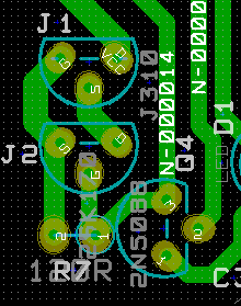
Apply the best rules for layout that you can, and I would do that in v1.2 as well. Nothing to lose aiming for the best. Lowest inductance, especially where it matters, use sense wires, etc. We've talked about these at length in the past. You can have a look at the pcb picture that I posted earlier. I did my best to get the best layout there.
I will look carefully at your pcb.... I have already built 14 shunts and consider v1.2 to be exceptional in performance but sometimes I get instability and hum, depending on the layout of the output cap.... I will let you know after some studying 🙂
My opinion about the stability issues comparison between this reg and v1.2 are based only on me building mine, and looking at the schematic of v1.2. I haven't actually built v1.2.
But Bill has talked much about this reg here, and his experience with it. If he's still using them, perhaps they proved to be stable and robust. I think he is the person who has used them the longest time.
But Bill has talked much about this reg here, and his experience with it. If he's still using them, perhaps they proved to be stable and robust. I think he is the person who has used them the longest time.
Apply the best rules for layout that you can, and I would do that in v1.2 as well. Nothing to lose aiming for the best. Lowest inductance, especially where it matters, use sense wires, etc. We've talked about these at length in the past. You can have a look at the pcb picture that I posted earlier. I did my best to get the best layout there.
@Iko, is this your last schematic?
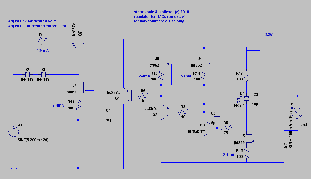
The trace from J1's source is going to J2's source instead of the drain. Fixed error
post1259,
Q2 & J6 should be fed from the supply rails, not from the measurement rails.
What voltage (Vdg) is across the BF862 when they are set to 2 to 4mA?
I think you should be using a low Vpinch off for some of these locations, particularly J5 and maybe J6.
Q2 & J6 should be fed from the supply rails, not from the measurement rails.
What voltage (Vdg) is across the BF862 when they are set to 2 to 4mA?
I think you should be using a low Vpinch off for some of these locations, particularly J5 and maybe J6.
Last edited:
Could you link or post the good one with no errors?
I don't have a link. Look back in this thread, and find the one I posted last and uses power mosfets for the CCS and shunt.
- Status
- Not open for further replies.
- Home
- Amplifiers
- Power Supplies
- My take on a discrete shunt voltage regulator