Really? Have a look:
Power Chokes: Large Transmitter Applications
In particular, let's consider the Basler choke near the end of the page. 1 Henry, DCR of 10 ohms, 4.5A, for only $325 plus shipping. These seem surplus, but it never bothered me buying used. Run psudii and see what ripple you get with this. Or simulate it in ltspice. Do a CLC with some large capacitors.
Hammond Mfg. - Racks & Rack Cabinets, Small Enclosures, Electrical Enclosures, Transformers, Outlet Strips
The 159 models are very good and 2 of the biggest ones per rail give a very good simulation results to me. Haven't built the prototype psu yet. Cost is around 20€ each.
I'll be using something similar before the regulator in the VAS and driver stage psus.
If you do a search here somebody else used those chokes (159ZL) and the opinions were good.
I dont agree with Mr. Duncan. I prefer power amps with very stiff PSU - IMO they have the best dynamics and PRAT (i.e. The ASR Emitter). Of course the amp must work well before clipping.
Yes there is argument. Even in valve amps some say that the limp valve rectifier gives some of the ''louder than its Watt'' feeling, others say make it with semi diode bridge and design for more output.
Really? Have a look:
Power Chokes: Large Transmitter Applications
Oh, my favorite on that page would be the Magnatran filter reactor. 3 Hy @ 15 dca @ 1200v, 380 cycles. DC resistance = 6.6 ohm, operating volts = 25 kvdc. 59 gallon oil (may contain PCB). 36" x 59" max dimensions. New, never used. Yeah baby, groovy! Very shaggadelic for only $9500 😀
Sure would impress the women folk.
Ran your suggested CLC sim and I was off by an order of magnitude in my thinking about chokes. So much to learn...
Here's what I was wondering; Shunts seem to create the most heat when the current demands are low - basically disipating the difference between the maximum current and the current draw in the form of heat. Do I have this right?
If so, it seems like you're really chasing the heat curve as you try to supply the output devices.
As an alternate supply for the output devices, I was running simulations on a capacitance multiplyer at higher voltages and currents using multiple devices to stay within the SOA of the devices. The sim said it would work... It seemed to show that it made the most heat at maximum current draw, with propotionately less heat at lower current draw. So, for a class A/B amp (that isn't run continously against the rails) a cap multiplyer would have a lower heat penalty. Could it get to the low ripple of a shunt? When does the ripple get swamped by the big current switching artifacts of the output devices of a class B amp?
Hey, sorry I haven't seen your post.
Yes, that's right.
True, a cap multiplier would indeed dissipate less heat. But remember that the output impedance of the cap multiplier is large. So the moment your amp draws suddenly some significant current, the rail voltage will suddenly drop. It has to. The shunt will fight to give all that suddenly requested current AND to keep the voltage rail constant. The lower the output impedance, the better it will do this. The cap multiplier cannot do it.
OK, I've been running again quite a lot of tests. Here's an image that might be of interest, regarding the noise. This is rev 5k positive, with about 11V output, 430mA idle current, a 33uF cap right on the output of the regulator. The load is a power mosfet biased to draw about 200mA DC, located about 7 to 9cm away from the regulator. Across the load there's a 47uF bypass cap. I put this here to make sure that people who bypass their loads with caps don't run into trouble. Up to 40MHz I could detect no nasty oscillations, even when I applied a sine wave to the mosfet thus making it draw variable current as well.
Here's what I was wondering; Shunts seem to create the most heat when the current demands are low - basically disipating the difference between the maximum current and the current draw in the form of heat. Do I have this right?
Yes, that's right.
If so, it seems like you're really chasing the heat curve as you try to supply the output devices.
As an alternate supply for the output devices, I was running simulations on a capacitance multiplyer at higher voltages and currents using multiple devices to stay within the SOA of the devices. The sim said it would work... It seemed to show that it made the most heat at maximum current draw, with propotionately less heat at lower current draw. So, for a class A/B amp (that isn't run continously against the rails) a cap multiplyer would have a lower heat penalty. Could it get to the low ripple of a shunt? When does the ripple get swamped by the big current switching artifacts of the output devices of a class B amp?
True, a cap multiplier would indeed dissipate less heat. But remember that the output impedance of the cap multiplier is large. So the moment your amp draws suddenly some significant current, the rail voltage will suddenly drop. It has to. The shunt will fight to give all that suddenly requested current AND to keep the voltage rail constant. The lower the output impedance, the better it will do this. The cap multiplier cannot do it.
OK, I've been running again quite a lot of tests. Here's an image that might be of interest, regarding the noise. This is rev 5k positive, with about 11V output, 430mA idle current, a 33uF cap right on the output of the regulator. The load is a power mosfet biased to draw about 200mA DC, located about 7 to 9cm away from the regulator. Across the load there's a 47uF bypass cap. I put this here to make sure that people who bypass their loads with caps don't run into trouble. Up to 40MHz I could detect no nasty oscillations, even when I applied a sine wave to the mosfet thus making it draw variable current as well.
Attachments
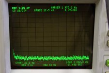
Forgot to mention, the circuit was not protected from RF in anyway, and I didn't use the proper probe connection so I was pretty sloppy. Should be done again, the results should be even better.
Is the up hill near 20Hz related to a not so big Vref filter cap, or the analyzer picks up there due to its 20Hz limit spec?
That's right, analyzer thing at the edge of it's frequency limit. I mean, it's not so great a result, but it's honest. The main question I wanted to answer was: does the regulator oscillate with a capacitive load?
8-9cm from load, not in a metal box of its own, some local cap on the load, i.e. typical real DIY use it will see. Was it remote sensed for that analyzer photo?
Yes, remote sensing. Air sculpture with long leads on all parts, I did not try to be tidy. The simulator doesn't agree with reality this time, but then, I've learned my lesson about how much and when to trust a simulator. Reality rules.
Stability. This is one of the tests I've tried for every new version, to add all possible parasitic wire inductance. But Bill mentioned that he thought the regulator oscillates with a capacitive load. So when I added a capacitor at the load the regulator indeed oscillated, in simulation. But here's the surprising fact. Your v1 also oscillates if all wire inductance is added and with a capacitive load. In fact every version we had behaved like that. I knew this couldn't be because in reality v1 has been used by so many people without oscillating. Indeed, the simulator is wrong about this.
For this test Rs was just two solid wires, not coax. Told you, sloppy build 😀
For this test Rs was just two solid wires, not coax. Told you, sloppy build 😀
Oh, so I forgot to qualify this 8nV/rtHz figure. The spectrum analyzer gives exactly 8nV/rtHz with a 50 ohm bnc terminator connector at its 50 ohm input. So the regulator noise is not above the noise floor of the HP 3585A. 😀 Now I really have to finish the noise preamp to get any meaningful measurement.
Attachments

So your HP its good to show possible oscillations but its SNR of 80dB isn't helpful for what you would like to quantify now. So far so good though.
Come on Iko, you will do.
An externally hosted image should be here but it was not working when we last tested it.
Yes, remote sensing. Air sculpture with long leads on all parts, I did not try to be tidy. The simulator doesn't agree with reality this time, but then, I've learned my lesson about how much and when to trust a simulator. Reality rules.
Ikoflexer,
Good test! At least it shows that putting a high ESR cap at the load does not cause any resonance. However, I would hesitate making a conclusion though. In your test, both the 33uF output cap and 47uF output cap have considerable ESR therefore there is no surprise that the circuit in whole did not resonate, I think in simulation if you put enough ESR it won't resonate neither, same result as in your real test.
You could try this: remove your 33uF electrolytic capacitor and leave only the 4uF film cap at the output. Take out the 47uF and put a small value film cap of 0.01uF or 0.1uF MKP right at the load. Now see if there is any resonance and see if it agrees to simulations. You could also try some pF values. Two parallel wires of 16awg on perfboard of 1cm length would have 6pF and if such wires go as long as 10cm in rail tracks there would be 60pF there! If you find resonance in that case, you may put the 33uF back at the output and see if it kills the resonance, and if not, try adding the 47uF back at the load and may pad it with some resistance.
Please don't get me wrong. Let me state again (and again) that the regulator is very well designed and it is very stable. What we are addressing here is not about the fault of the regulator, which we have not found any. The issue is that some regulator output inductance, rail wire inductance and load capacitance form a LCR resonante circuit, unless there is sufficient R (like high ESR) there to damp it, it can resonate (wildly or mildly, depending on the values). I guess in your previous test the load capacitance (of the MOSFET) was basically none so it may not be qualified to be a capacitive load, or it is so small that can be ignored (wire resistance is enough for damping). Your 47uF (high ESR) capacitor works well damping any possible resonance, too.
The purpose of such tests is to find the high ESR bypass capacitor at the load, or C + R, that is appropriate for the typical capacitive load.
Regards,
Bill
Last edited:
Ikoflexer,
It has been discussed previously that running at higher current due to changes of gm of the MOSFETs the output impedance can even be reduced! However, no figures or charts have been given for comparison. Is your published impedance plot based on about 400mA you normally run?
I am wondering if you could post a few simulations with CCS run at 100mA, 200mA and 500mA so that users can make their choices. Perhaps even with lowish current the impedance of the regulator is still so low that wire resistence dominates?
I am currently running them at 135mA and the sonic is excellent. My heatsinks are rather small so I prefer running them at 100mA, but don't know if the increased impedance would introduce audible difference or not.
Thanks in advance.
Regards,
Bill
Here Bill, something like this? I stepped R1 as 16R 13R 10R 7R 5R 3r 1R 0R5 which would give a current limit of 170mA 208mA 270mA 386mA 541mA 901mA 2.7A 5.4A respectively. The simulated output impedance behaves as you can see in the attached plot.
My worry wouldn't be that the lower current doesn't give one enough output impedance, but that higher current will easily lead to instability. I haven't done enough tests at very high current so I can't vouch that it's problem free.
My worry wouldn't be that the lower current doesn't give one enough output impedance, but that higher current will easily lead to instability. I haven't done enough tests at very high current so I can't vouch that it's problem free.
Attachments

- Status
- Not open for further replies.
- Home
- Amplifiers
- Power Supplies
- My take on a discrete shunt voltage regulator