lumanauw said:Hi, Workhorse,
It is very small, like the size of 1000uF/25V 😀
If small things were cute one, than what about the Big things.........😉
hmmm too crude...the 220K effects both the closed-loop gain as the Vidle setting.. allthouth the amplifier will run open loop in practise anyway as a gain of 100x will leave no feedback to spare.. any idea what the output impedance will be? in the 2-to-10s maybe?
Output impendence is roughly 2 ohms. I've built and listened to it for a couple of days now, not bad at all, suprisingly solid bass but the highs aren't as good as I'd hoped.
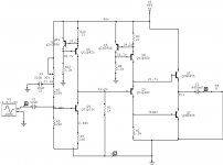
NE5534 output stage
😎
lineup here
( by the way I have began project01 Class A Amplifier at lineup diy audio website )
😎
tschrama added CCS, current source
which of course is natural solution
in this simple output stage by jerluwoo
If we add some resistor based control of current in output pair
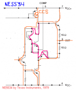
we are soon arriving at year of 1979
where some Amplifier IC designer had the same idea
for an output stage.
It is not easy to see from NE5534 simplified! schematic
so, I might help you all a little bit.
In fact most everyone a member at www.diyaudio.com
has some time listened to music through this output
or even have several audio devices with this very same circuit
Of course talk of NE5534, use in millions and millions of manufactured
audio machines: amplifier, CD-players wetc. etc.
To control the iidle current in output
is added the stuff that is red marked in my drawing
This little constant voltage part, together with those two 15 Ohm resistors
will keep the current at a fairly constant level.
References used:
NE5534 Texas Instruments datasheet
This article
and attached image with drawings
was delivered to you
by
lineup audio 😉
😎
lineup here
( by the way I have began project01 Class A Amplifier at lineup diy audio website )
😎
tschrama added CCS, current source
which of course is natural solution
in this simple output stage by jerluwoo
If we add some resistor based control of current in output pair
we are soon arriving at year of 1979
where some Amplifier IC designer had the same idea
for an output stage.
It is not easy to see from NE5534 simplified! schematic
so, I might help you all a little bit.
In fact most everyone a member at www.diyaudio.com
has some time listened to music through this output
or even have several audio devices with this very same circuit
Of course talk of NE5534, use in millions and millions of manufactured
audio machines: amplifier, CD-players wetc. etc.
To control the iidle current in output
is added the stuff that is red marked in my drawing
This little constant voltage part, together with those two 15 Ohm resistors
will keep the current at a fairly constant level.
References used:
NE5534 Texas Instruments datasheet
This article
and attached image with drawings
was delivered to you
by
lineup audio 😉
Attachments
After listening for several hours to my latest posted schematic, I have to give it a thumbs up. It has the wonderful treble I liked so well in the first circuit, easier to push to full output and, seems much more stable to temp. drift. 😉 The only feedback is emitter degeneration of the input stage. The wonderful treble sound is probably from heavy 2nd harmonics which sounds very musical and voice seperation is very distinct.

jerluwoo said:After listening for several hours to my latest posted schematic, I have to give it a thumbs up.
....
The only feedback is emitter degeneration of the input stage.
Great!
I am quite a bit surprised that your simple amplifier works so well.
I guess those 2N3055 transistors are very well matched.
They are obviously from same batch, package, and machine in same korean factory.
( matched= Have very much same chararcteristics, values. When we buy we can sometimes be unlucky that those transistors are coiming from different machines at different times, when they were made in semiconductor factory. Even some can come from another factory and in another country! )
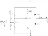
The bootstrap ( C2, R3, R8 )
and all those BASE and EMITTER resistors in Output transistors
will further help to make amplifier behave good. ( R10 .. R17 )
Anybody else want to try jerluwoo design?
Would be really interesting to know, if everybody get same good results.
On my papers it is too simple amp construction to give good result.
But who will care about any of my papers, if reality shows an amplifier plays music
and does this in a very good way 🙂
Congratulations, jerluwoo!
Good working.
thinks lineup
lineup audio lab
>> lineup.awardspace.com <<
Thanks for the encouragement Lineup. Like many of the overly simple designs on the forum it is hard to believe they can make nice music. I built this amp in Multisim 8 pro earlier and to my very large suprise (and consideration of how accurate or not the sim is) this circuit arrangment produced a mere .465% thd at full output just before clipping. Interesting also is that the least distortion was found when vout = 1/2 supply + 1volt. Some may think that isnt so good ,but, consider that it uses no corrective feedback and many commercial amplifiers are rated at nearly 1% thd at full power is something. And again ,if the sim is fairly accurate, it can reproduce to nearly 500khz at full power. If I were more knowledgable I would use ccs's in the circuit but I havn't mastered that yet.
I have also built this morning a version running at 40v and 3amps idle giving nearly 20 watts into 8 ohms and close to 30 into 4. With my sensitive speakers this is almost ear splitting but still has a wonderful sound.
As for the transistor being matched they were bought at radioshack off the self (they only have 4 at a time on hand, seems no one in my area does much diy electronics) but measured on my dmm there was quite a difference but it seems not to make much of a difference in sound quality from amp to amp( have built 3 of them so far including my latest 40v one).
jerluwoo said:Thanks for the encouragement Lineup.
Like many of the overly simple designs on the forum it is hard to believe they can make nice music.
I built this amp in Multisim 8 pro earlier and to my very large suprise (and consideration of how accurate or not the sim is) this circuit arrangment produced a mere .465% thd at full output just before clipping.
....
As for the transistor being matched they were bought at radioshack off the self (they only have 4 at a time on hand, seems no one in my area does much diy electronics) but measured on my dmm there was quite a difference but it seems not to make much of a difference in sound quality from amp to amp( have built 3 of them so far including my latest 40v one).
So if we would use closely matched 2N3055, it would possibly only make better!
Shows that your circuit is forgivng for transistors have a bit different values.
I am not much for simulation.
I use my head, pocket calculator, pencil and paper, most of the time.
But I got Electronics Workbench DesignSuite v9 on a CD
which came with an electronics magazine I have subscribed to.
For 15 years in a row now!
I have quite a collection of them previous issues. 15 years x12 issues should make more than 180 magazines full with schematics / projects. And several 100-reds of a amplifiers.
I am talking about http://www.elektuur.nl/ ... http://www.elektor-electronics.co.uk/ ... http://www.elektor.fr/ ... dont know what called in Spanish
which comes in serveral languages.
I am sure you know about this.
Anyway, I installed DesignSuite9 free version ( limited number of components ) only a few days ago.
Really nice with all them testinstruments and oscilloscopes.
Fourier test and all kind of things I dont know too much about.
I like it!
It will give a good complement to my papers with drawn circuits.
At least will tell if I have done something REALLY bad.
Your results with this amplifier using Multisim, considering you are still in heavy learning,
shows how good help such a software can be.
It can NOT simulate reality and practical, mechanical build and wiring and such,
but surely can give a hint, if in right direction and if a change in a circuit is FOR BETTER or FOR WORSE.
The files saved from my Multisim are called circuitname.ms9.
Anybody knows what other File types I can EXPORT using multisim?
I like to be able use someting else, than just save .ms9 and have to take screen captures of my schematics to get pictures ...
thanks
lineup audio lab
>> lineup.awardspace.com <<
Another fun little tidbit with this circuit is that it can be used bridged very easily. Since it has only 2 stages and the output is inverted, by simply placing a resistor of about 33k at the output and running it to the input of a second amp you have a bridged amp. If you can match the vouts very close the output cap can be removed.
I think it gives power enough
without make it complicated and introduce new distortions
by bridge.
Tou may want to try Constant Current Source = CCS instead of bootstrap
which is a good advice from tschrama.
There are more than plenty information on CCS at this forum.
Make a search, and you will find many many small CCS circuits
you can use to replace those 2 resistors and 100 uF electrolytic capacitor.
Even if distortion will not be much lower using CCS
it has the added function of increasing PSRR. ( power supply rejection ratio )
Same as say the amplifier will be less sensitive, reject variations and garbage from the V+ power supply line.
When input stage, second stage and output transistors SHARE
same postive supply line,
there WILL BE interference from those with more Current ( from output )
to those with less current = input stage.
To stop this possible interference distortion, we can use:
1. Capacitor + Resistor filtering ( RC-filters )
2. Constant Current Sources.
lineup
Playing with this circuit a bit more in multisim 8 I found that the THD starting at 20hz is .348% and slowly rises to .454% at 20khz.
If this holds simularly true to the actual circuit (which I think seems to be true,remember that wonderful treble I like so much) then it is no wonder this amp sounds so nice. Nearly all amps I've seen, the distortion rises very quickly above 1khz, most being say 1% at 1khz and ending up at 10% by 20khz. Only example figures of course but true with a lot of amps.
If this holds simularly true to the actual circuit (which I think seems to be true,remember that wonderful treble I like so much) then it is no wonder this amp sounds so nice. Nearly all amps I've seen, the distortion rises very quickly above 1khz, most being say 1% at 1khz and ending up at 10% by 20khz. Only example figures of course but true with a lot of amps.
Well I no longer believe the distortion analyzer in mutisim 8 has any accurracy. After buiding an overly simple class b and testing it ,it showed to have .02% thd when crossover distortion was visable on the ocsilliscope. So throw the previous distortion figures for my circuit out as they arent accurate at all. 
I did see an improvment in the thd when using an rc filter in the line to the base of the input trans but after finding how innaccurate the sim is on such things I dont know if it actually made that much of a difference. Will have to incorporate it into my circuit and listen for a bit.
I did see an improvment in the thd when using an rc filter in the line to the base of the input trans but after finding how innaccurate the sim is on such things I dont know if it actually made that much of a difference. Will have to incorporate it into my circuit and listen for a bit.
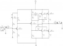
jerluwoo said:So maybe this arrangment is closer to what you are hinting at
Lineup
Keep your CCS current source for the VAS ( voltage amplification stage )
But you should put R1 ( 1 kohm ) from collector of Q4 to Ground.
Volt Amp Stage will give: R1/R7 ~ x10 gain.
Makes no difference if is connected to Ground.
Now you will adjust the CURRENT from CCS-1, Q8,
by putting in a (variable) Resistor between +40 Volt and Q8 Emitter.
When you get like 21.3 volt again, this Q8 emitter resistor has got the perfect value.
( will supply Q4 + R1 with correct current level )
-----------------------------------------------
R8 must be REMOVED and replaced with a direct wire to V+.
This way the CCS-2 will supply a current =
~ 0.7 / R3
the voltage across base-emitter ( vBE ) of Q5 is something like 0.6 - 0.7 volt
like for most any normal transistor
-----------------------------------------------
You should remove the Q7 part.
For input transistor, use the same RC-filter as I have in this Class A Headphone Amplifier
schematic:
http://www.diyaudio.com/forums/showthread.php?postid=999712#post999712
At very low ( uA ) currents, a Resistor / Cap, RC-filter is a better and easier solution.
Let me see your next version, soon.
Interesting with your ideas.
May give me new ideas for new circuits.
lineup - amp designer 🙂
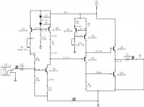
Here is the revised schematic. Thanks for the input and easy explanation for setting the ccs current Lineup. You'll notice that the current required in the VAS stage is more than double the original because of the orientation of the load resistor to ground. I will have to construct this circuit soon to compare the sound with the non-ccs version. Then I'll have to figure out a better power supply than my simple clc.
Attachments
Latest schematic with ccs's is now up and running. Biggest noted differences are that the bass sounds much more controled and deep and it is super quiet. Even after removing the L from the CLC supply filter I have to put my ear next to the speaker to hear any noise. It still retains its lovely treble and the mids a bit smoother. It takes about 15 mins for it to settle but bias currents and voltages remain with practically no drift. It would be wonderful to have some of you built and experiment with this circuit and give me some feedback on your results.
Word of warning for would be builders, Everything Should be Heatsinked and built with Overated parts. All the larger ccs and all amplifying transistors get very warm especially the input/voltage stage.
Word of warning for would be builders, Everything Should be Heatsinked and built with Overated parts. All the larger ccs and all amplifying transistors get very warm especially the input/voltage stage.
jerluwoo said:Latest schematic with ccs's is now up and running.
Biggest noted differences are that the bass sounds much more controled and deep and it is super quiet.
Even after removing the L from the CLC supply filter I have to put my ear next to the speaker to hear any noise.
It still retains its lovely treble and the mids a bit smoother.
It takes about 15 mins for it to settle but bias currents and voltages remain with practically no drift.
It would be wonderful to have some of you built and experiment with this circuit and give me some feedback on your results.
Word of warning for would be builders, Everything Should be Heatsinked and built with Overated parts. All the larger ccs and all amplifying transistors get very warm especially the input/voltage stage.
to make less heat on first input transistor:
please make R1 and the other resistor 2 x value ( 100 ohm / 1.000 ohm )
220 ohm / 2.200 ohm
will make only 50% watt
Power watt = Volt x Current
Power watt = (Volt x Volt) / ohm
The more ohm, the less power = less heat
is much better for a small signal transistor
I would maximum run a small signal, input transistor, like 2N3904, at 0.200 watt or max 0.300 watt
that is to make the FIRST CCS, current source
only put 5 - 15 mA, milliAmpere
in that first transistor
Glad your amplifier works so good in reality.
I am very happy about it, jerluwoo
yours, ever a friend
lineup, at
http://lineup.awardspace.com/
- Status
- Not open for further replies.
- Home
- Amplifiers
- Solid State
- My simple class a approach