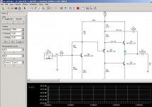
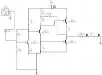
As measured the lower output trans supplies about 2/3 of the total ac current through the load. At full output with 1.5 amps through the load, about 1 amp flows from the collector of the lower trans to the load and 500 milliamps from the emitter of the top trans. So what am I missing about how the output works 😕
So I'm thinking maybe I've got it backwards maybe, the "phase splitter" trans and the lower output trans are forming a silazki (however you spell it) pair with the top output trans as the load?
welll maybe this circuit is driving my head around and I am actually the one that doesn't got it ... anyways .. if it sounds good, it is good.... never mind what I say..


Saw the bootstrapping on your sim and checked it out. Seems that bootstrapping equals the ac current from both to push pull output. Will have to mod one of my circuits to try it out.
By the way, I am using the models from On Semi website in my sims. The actuall outputs I,m using are mje3055t's.
By the way, I am using the models from On Semi website in my sims. The actuall outputs I,m using are mje3055t's.
Modified one of my built circuits with a bootstrap. It still sounds very good but seems to have lost some of that wonderful sparkle in the treble the other circuit has. Although it is only a minmal loss it may be a good trade off for a more consistant bias.
oops typo on the schematic, 200k resistor should still be 100k.
oops typo on the schematic, 200k resistor should still be 100k.
Attachments
Hi,
I ilke such circuits.. did you read Nelson PLH article.. it's a good read about such topologies... but how did you set the idle output voltage?
I ilke such circuits.. did you read Nelson PLH article.. it's a good read about such topologies... but how did you set the idle output voltage?
Anyways.. you should really read Rod Elliots commented article about the JHL 10Watt Class A amp.. it helps to get a good understanding of the topology..
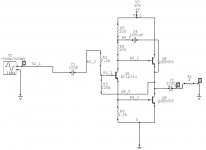
meanwhile I have attached a variation that not only has no negative (loop-) feedback.. but also solves the idle Vout setting..
regards, Thijs
meanwhile I have attached a variation that not only has no negative (loop-) feedback.. but also solves the idle Vout setting..
regards, Thijs
Attachments
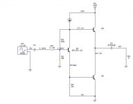
In my circuit ,vout is set simply by the 220k resistor. Making it a 1meg pot and the input resistor a 10k pot, adjust the 1 meg to get 1/2 supply vout and then adjust the 10k pot for 100-1 ratio to set feedback. Crude ,yes, but it works.
Hi,
What should be the voltage rating of C2=4700uF? If the rail is 30V, should the cap rated min=30V, or it can get away with voltage of 5 or 10V rating? I think the drop of voltage in this C2 is very small, no need to have the same voltage rail rating?
4700uF/5V rating is cute cap 😀
What should be the voltage rating of C2=4700uF? If the rail is 30V, should the cap rated min=30V, or it can get away with voltage of 5 or 10V rating? I think the drop of voltage in this C2 is very small, no need to have the same voltage rail rating?
4700uF/5V rating is cute cap 😀
I would recommend at least 50v for the output cap. Popped a 35v, but it may have been faulty to start.  Minimum would be 35v because the output voltage swing will put near 30v across it.
Minimum would be 35v because the output voltage swing will put near 30v across it.lumanauw said:Hi,
4700uF/5V rating is cute cap 😀
Hi Golliath Killer_David,
What is CUTE thing in that cap??🙂 😉
K a n w a r
- Status
- Not open for further replies.
- Home
- Amplifiers
- Solid State
- My simple class a approach