Hello,
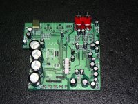
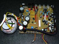
This are my last DAC. The pictures are self speaking.
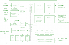
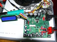
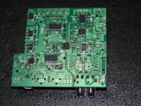
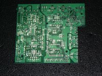
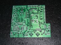
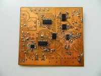
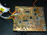
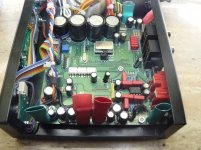
First pictures are with test boards single side and the last are with the finished pcb, double side. The last one it is the block diagram.
This are my last DAC. The pictures are self speaking.
First pictures are with test boards single side and the last are with the finished pcb, double side. The last one it is the block diagram.
Attachments
-
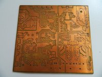 First PCB (Ver75).jpg456.1 KB · Views: 1,878
 -
 Block Diagram.png41.8 KB · Views: 972
 -
 P1160747.JPG519.2 KB · Views: 869
 -
 P1160742.JPG768 KB · Views: 686
 -
 P1160739.JPG784.1 KB · Views: 687
 -
 P1160738.JPG785.3 KB · Views: 1,236
 -
 P1160737.JPG812.6 KB · Views: 1,269
 -
 P1160733.JPG800.4 KB · Views: 1,373
 -
 Picture 004_.jpg220.1 KB · Views: 1,401
Quite impressive, that is what I call true DIY 
Why that high speed isolator? Wouldn't a single one for the µcontroller suffice?
Why that high speed isolator? Wouldn't a single one for the µcontroller suffice?
Hi,
I forgot to mention that the output analog part are galvanically isolated from the digital input part. I used galvanic isolation to cut any ground loop that can occur and any noise that can be transmitted from digital schematic side to analog side through the ground.
The high speed izolator are for data and low speed are for commands. The data clock for digital filter are as high as 24.576MHz.
What type of high speed isolator are you using? You have considered it's propagation delay, I assume.
Are your PCBs made in Romania?
Are your PCBs made in Romania?
Yes .... and
I do not understood exactly yous questions regarding propagation delay, but yes. The propagation delay are the same on all data lines and it is not so important the exact values or how big are. The commands from µController are not time connected to signal from data lines.
The PCB are made in Romania. Was very expensive, more that I expected, but the quality are god.
I'm not a fan of audio grade expensive components, only god quality from verified source. It can be seen on PCB this.
The components are noted on block diagram.
Last edited:
I remain with some PCB and I already work to another version.
To sound of this DACit is very detaliated and the stage image is the best of all DAC I have listened ( it is true that they were not the first in the charts).
If somebody are interesed, please send me a mesage.
To sound of this DACit is very detaliated and the stage image is the best of all DAC I have listened ( it is true that they were not the first in the charts).
If somebody are interesed, please send me a mesage.
Last edited:
I already see that the discussion is old.
However'm curious where you use this device ?
It has the same ....... a impressive case?
However'm curious where you use this device ?
It has the same ....... a impressive case?
Last edited:
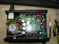
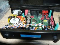
I use at my home.
I have a box, custom made, from iron sheet painted black in electrostatic field.
It is not in the classical style spread among the great audiophiles builders with a lot of frippery, wooden casing and so on.
It is more in the "industrial" style.
Unfortunately, the case is not engraved, as I actually would have liked.
It also aims to protect against electrical noise.
I tested the shielding factor of such metal box by putting a cell phone on the housing while it was in conversation and even in the break between songs, I don't managed to find a position in which to hear classical mobile phone jamming.
the case...
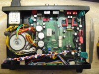
As I promised I put some pictures with the used housing.
It is custom made from steel painted on black.
As I promised I put some pictures with the used housing.
It is custom made from steel painted on black.
Attachments

Impressive realisation...
I wonder only about the grounding point you use over the toroid central fixing screw. I assume this screw it is in contact with the metallic chassis on the bottom of the transformer.
The ground wire (yellow/green) you use and/or the rest of the wires connected in that point (pictures), it may form a turn (loop) and some AC currents it may be induced so into the ground connection, by the toroid coil itself... Such wiring/connection is to be avoided when using a toroid. Do you not have problems by choosing a such ground connection?
Personally I would like to connect the ground wires right on the chassis, and let free the top of the toroid screw (as recommended when using a such type transformer)...
No problem Coris, the audio analog part are galvanic isolated.
I explained at the beginning that the digital part of the schematic are completely isolated by the DAC, filters, and volume control - the analog part of the equipment.
I explained at the beginning that the digital part of the schematic are completely isolated by the DAC, filters, and volume control - the analog part of the equipment.
I read your explanation again and you are right but fortunately because I have galvanic isolation I have no problem with this power supply noise probably is induced in the Earth connection. At the first opportunity, when I will open again, I will change my connection to the Earth.
Thanks for giving me attention.
Thanks for giving me attention.
I corrected the ground connection Coris, thank you!
I change the connection point to the screw that fix the power socket.
I do not noticed any change in sound. but it is better to be correct routed.
I change the connection point to the screw that fix the power socket.
I do not noticed any change in sound. but it is better to be correct routed.
Last edited:
I had the opportunity to meet Bogdan and listen @sesebe's DAC yesterday on two systems:
first one was a diy speaker system run on a fairly good Yamaha amplifier , which wasn't finished on the subwoofer side, but for the most part of the job the sound was cristal clear, delivering a good punch and well defined over 200hz while the base suffered a bit because he's using two subwoofers and his listening room is less than perfect causing some resonances at around 200hz as @sesebe showed me when taking some real measurements with a microphone.He's still fighting with his speaker's filters, but i allready know that his system simply needs a specialized room for listenings , his living room being far less than perfect for a fine tuning.
Second ...i just used my Bayerdynamics DT880 pro and his Samson studio headphones and the sound was really good on the dac headphones output .
Well...we don't have the most expensive gear to evaluate audio systems , but we did well enough for a first .
I 'm glad that i met him and i found a really passioned audio guy.
His means might look modest, but the degree of dedication and passion for a good sound was really impressive.
Hello all,
It is time to design an improved new version of my DAC and I'm thinking maybe to change the DAC chip that I used.
Can you recommend a different DAC chip that I can use?
I still have some desires:
If there are already this discussion please redirect me to that topics.
It is time to design an improved new version of my DAC and I'm thinking maybe to change the DAC chip that I used.
Can you recommend a different DAC chip that I can use?
I still have some desires:
I do not want something from ES family, if possible
I do not want something with current output
I do not want something with integrated filtering on analog side
If there are already this discussion please redirect me to that topics.
What would you think about trying any iout dac and a balanced version of my i/v stage idea with lower noise high hfe pnp transistors , better op-amps like your lm4562 and passive filtering ? I'd like to see someone else giving a try to my idea even if the results would be less than ideal.
https://www.diyaudio.com/forums/dig...cd-players-enhancing-noise-6.html#post5689006
The sims with a LT1115 and bc337/40 as input transistors show about 85...88db thd with predominantly even harmonic content dependent on the input transistor bias and feedback with a simple sine input. I would recommend to try the tape-head coupling just for fun, but , if you want to give it a try , please try first a better spice model than mine for an i/v section suitable to your high end dac's and tell me what you think about that!
Don't change your dac yet! I've listened to your dac and it was good sounding already.
One day i found an old Toshiba cd player and what amazed me was the passive filter attached right at the output of the DAC.
You can see it in my attachment and because we had some discussions in the past about what you could measure at the output of a digital system , maybe you'd take a further step to actually improve a filtering system than just "swapping dac chips " .I know that you're a very competent engineer who has the right tools to measure that noise too 😉
Attachments

Sorry, i just realized that you have a v-out dac.The toshiba player in the photo had a 16 bit v-out dac , probably way noisier than yours. I can't delete my previous post now.
- Home
- Source & Line
- Digital Line Level
- My second try on digital side