Zobsky, are you reading my mind or something. 😱
I figured if these aren't ripole compatible I would try a sideways W like the one in your pic.
BTW, thanks for doing all the hard work for me. 😀
I figured if these aren't ripole compatible I would try a sideways W like the one in your pic.
BTW, thanks for doing all the hard work for me. 😀
theAnonymous1 said:Zobsky, are you reading my mind or something. 😱
I figured if these aren't ripole compatible I would try a sideways W like the one in your pic.
BTW, thanks for doing all the hard work for me. 😀
Now you don't have to feel bad about not completing your project before mine.
I'm waiting to see if I can get any responses before I glue the first cab up. If not, I'll clamp up something and find out myself.
Zobsky ,
By making the wings different lengths you will probably distribute the resonant frequencies. If they are equal the frequencies will coincide and make the resonance worse. However turned on its side and kept on the ground should affect it as the wall on one side ( the ground ) would be semi 'infinite' as compared to the other smaller wooden sides.
Looks like lots of experimentation is called for.
Cheers.
Re: To trim or not to trim
If you want to go the U-way - why do you plan a W up front anyway? Just for impulse compensation?
The radiation pattern would become more of a cardioid - which could be good or bad. Depends on what you want to achieve. I read from quite some people that they prefer their U baffles unstuffed.zobsky said:Should I make this a hybrid W-U baffle by letting the wings extend beyond the "V" and stuff the cavity or should I truncate it at or near the "V".
If you want to go the U-way - why do you plan a W up front anyway? Just for impulse compensation?
From practical experience I don´t see any significant distribution of resonance. It will just lock on another frequency. And as ashok stated: You already have unequal length by making the floor one side of the U.Also, would I benefit from making the wings unequal lengths?
Re: Re: To trim or not to trim
I'm not sure about zobsky, but I was thinking of this exact configuration to minimize the height. My mids/highs will be on top and two 15" drivers on the bottom will set them too high.
Whats is "impulse compensation" and why would a W have this and not a U?
Rudolf said:If you want to go the U-way - why do you plan a W up front anyway? Just for impulse compensation?
I'm not sure about zobsky, but I was thinking of this exact configuration to minimize the height. My mids/highs will be on top and two 15" drivers on the bottom will set them too high.
Whats is "impulse compensation" and why would a W have this and not a U?
Re: Re: Re: To trim or not to trim
Point taken 🙂theAnonymous1 said:I'm not sure about zobsky, but I was thinking of this exact configuration to minimize the height. My mids/highs will be on top and two 15" drivers on the bottom will set them too high.
The cones moving forward and backward will make the frame react with a movement in the opposite direction. In the W frame the tilted cones are moving half forward/backward and half up/down. Since in the vertical plane the cones are always moving in opposite directions there is no resulting vertical force into the W frame - only the horizontal fraction.Whats is "impulse compensation" and why would a W have this and not a U?
I always wondered whether and to which degree "impulse compensation" is audible.
Clearly, it cannot harm (one can als achieve "perfect" impulse compensation by mounting 2 woofers such that their cones move in exact opposite direction).
My Y-baffles are single woofers and are not very heavy (aroung 10 kg) - although rigid enough, also because of their shape. When I put my hand on them on significant low frequency content, they to "tremble" a lot(even though they sit on spikes). I am thinking of making them heavier by adding a heavy top plate.
Rudolf said:
Point taken 🙂
The cones moving forward and backward will make the frame react with a movement in the opposite direction. In the W frame the tilted cones are moving half forward/backward and half up/down. Since in the vertical plane the cones are always moving in opposite directions there is no resulting vertical force into the W frame - only the horizontal fraction.
Thanks, .. I don't have a lot of room (floor space specifically), so some sort of compaction is necessary when working with these large drivers to avoid ending up with a wall of speakers, literally speaking !! .
Thanks for clarifying what you mean by impulse compensation. A real W (drivers facing each other would work better but I like the aesthetics of the design with drivers at 90 degrees better. ... sacrifices !!
Would both the arrangements below exhibit it - I still don't get what the advantage of magnet to cone mounting is, compared to cone to cone mounting, as the net moment of force should be similar (though not identical) in both cases?

It's not mainly on magnet to cone or cone to cone - although that also plays a part.
It's the direction of cone movement, which generates a force in the opposite direction. If both cones moves in the same direction (like in a 2 woofer U frame) the forces will sum up. If cones move in opposite directions(as in a ripole), the forces will cancel. Anything else will result in a force that is the vector sum of the two - like in your W baffle.
It's the direction of cone movement, which generates a force in the opposite direction. If both cones moves in the same direction (like in a 2 woofer U frame) the forces will sum up. If cones move in opposite directions(as in a ripole), the forces will cancel. Anything else will result in a force that is the vector sum of the two - like in your W baffle.
bzfcocon said:It's not mainly on magnet to cone or cone to cone - although that also plays a part.
It's the direction of cone movement, which generates a force in the opposite direction. If both cones moves in the same direction (like in a 2 woofer U frame) the forces will sum up. If cones move in opposite directions(as in a ripole), the forces will cancel. Anything else will result in a force that is the vector sum of the two - like in your W baffle.
I agree and understand that. I'm aware that my 90 degree mounting will result in a net force acting in the horizontal plane. What I want to understand is the pros / cons of symmetric cone to cone (one of my figures, ripole etc ..) vs cone to magnet (linkwitz W) mounting.
I think that is a totally different issue.
The cone to magnet arrangement in Linkwitz's subwoofer should reduce even order distortion, by making one cone move out of the magnet, while the other cone moves into it. The magnetic field in the gap is not perfectly symmetrical around the cone stop position and this arrangement helps correct this to some degree.
The cone to magnet arrangement in Linkwitz's subwoofer should reduce even order distortion, by making one cone move out of the magnet, while the other cone moves into it. The magnetic field in the gap is not perfectly symmetrical around the cone stop position and this arrangement helps correct this to some degree.
bzfcocon said:I think that is a totally different issue.
The cone to magnet arrangement in Linkwitz's subwoofer should reduce even order distortion, by making one cone move out of the magnet, while the other cone moves into it. The magnetic field in the gap is not perfectly symmetrical around the cone stop position and this arrangement helps correct this to some degree.
Thank you, . that is what I wanted to know (".. The magnetic field in the gap is not perfectly symmetrical ..") , .. same operating principle as the so called"push pull" amplifiers.
Ripol from HobbyHifi
Calvin,
You seem to have quite some experience with the Ripol. Would you be kind enough to give us some advice ?
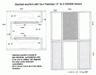
My friend & I built a Ripol based on the Ripol 12/2 from HobbyHiFi a couple of months ago, but with full side and bottom walls as per Linkwitz (see attached Drawing). Passive LC, & Mivoc AW3000 chasses. First impression deep base very impressive, but lacks dynamics.
Could be the amp (700W at 2 ohms) or cables, but could also be the Mivoc's .... Or are we loading the chasses too much (front opening about 106mm, 2x rear openings about 140mm each) ?
http://www.lautsprechershop.de/hifi/index.htm?/hifi/disub12_2.htm
(We wanted to be sure with the design before spending the money on a pair of Peerless'es.)
Thanks & Regards,
Patrick
Calvin,
You seem to have quite some experience with the Ripol. Would you be kind enough to give us some advice ?
My friend & I built a Ripol based on the Ripol 12/2 from HobbyHiFi a couple of months ago, but with full side and bottom walls as per Linkwitz (see attached Drawing). Passive LC, & Mivoc AW3000 chasses. First impression deep base very impressive, but lacks dynamics.
Could be the amp (700W at 2 ohms) or cables, but could also be the Mivoc's .... Or are we loading the chasses too much (front opening about 106mm, 2x rear openings about 140mm each) ?
http://www.lautsprechershop.de/hifi/index.htm?/hifi/disub12_2.htm
(We wanted to be sure with the design before spending the money on a pair of Peerless'es.)
Thanks & Regards,
Patrick
Attachments
Hi Pat,
what do Youmean with ´lacks dynamics´?
Is it the maximum SPL? Then You should know that 2x 12" drivers with medium throw capability are acceptable for listening to music (no HT) in smaller rooms up to 20-25m².
Is it the impression of a slow and sloppy bass?
Well then.....Mr. Timmermann´s concepts seem quite often to be more promotional projects than reasonable ones. The usage of drivers which are probabely ´pushed´ by the distributor, but are not neccessarily the right drivers for the application is very obvious.
In the first case a solution is to add more dipoles, in the latter case it is very probabely a matter of the driver, maybe a bit of the cabinets dimensions and definitely not a matter of the cables or amplification.
jauu
Calvin
Hello Calvin,
By lack of dynamics I meant slow & sloppy (not enough punch).
I also tend to think the chassis makes the difference. If I read your various posts correctly, you would also recommend Peerless SLS or XXLS, right ?
The room is about 20 sq m.
May I also pick your brains on a few questions I have in mind :
1) Any comments on the 106mm front exit and 140mm rear exit dimensions (height 330mm, depth 375mm, excluding all walls)?
2) How can I calculate the transmission line resonance frequency of the cavities in order to set the LC values of the EQ network?
Thanks in advance,
Patrick
If I'm allowed to make a few comments:
1. I haven't listened a lot of dipole bass units, but from what I've listened it looks like you're better off with larger diameter, higher Q drivers than smaller, long-throw cheap woofers needing lots of equalisation. I listen to a pair of Eminence Alpha 15A woofers in Y-Frames and there's plenty of both punch and extension. However, better and more expensive woofers like the Peerless might be better, but at another price.
WRT this, there an interesting topic on Zaph's site:
http://www.zaphaudio.com/lowxmax.html
2. I would suggest to actually measure the TL resonance rather than estimate it. It's safer. Actually, in a W frame, doesn't one have two resonances corresponding to the front and rear cavities ?
Cheers
Liviu
> If I'm allowed to make a few comments:
Of course, most welcome.
> looks like you're better off with larger diameter, higher Q drivers than smaller, long-throw cheap woofers needing lots of equalisation.
There are a few reasons I chose 12". First is how much room I want to allow for my subwoofer in a 4m x 4m sitting room. Secondly I do not need VERY loud base. So probably Peerless SLS is sufficient. XXLS is just to give it extra headroom, just like 100W class A power amps, when you use <10W 99% of the time.
And I don't have a TV, so no problem with magnets. 🙂
> I would suggest to actually measure the TL resonance rather than estimate it. It's safer.
That assumes that one has measuring equipment which has been well calibrated. Equipment we have, calibration we have not time to get round to yet, especially against room acoustics. Calculation gives a quick estimate and a good starting point.
> Actually, in a W frame, doesn't one have two resonances corresponding to the front and rear cavities ?
Is the frequency not only a function of the depth (length) of the cavity, and not dependent on the cross section ?
Patrick
EUVL said:There are a few reasons I chose 12". First is how much room I want to allow for my subwoofer in a 4m x 4m sitting room. Secondly I do not need VERY loud base. So probably Peerless SLS is sufficient. XXLS is just to give it extra headroom, just like 100W class A power amps, when you use <10W 99% of the time.
My subjective impression is that, with dipoles, one comes close to the speaker limits very quickly (especially with lots of EQ ). The limit is alway Xmax rather than power.
How big are your enclosures ? Like in the linked project ? My 15" have a footprint of 46x32cm, not to mention the Y shape which allows to "stick" them between other things in the room. Of course, you also need a reasonable distance to the back wall.
Is the frequency not only a function of the depth (length) of the cavity, and not dependent on the cross section ?
You're right, I had different lenghts in mind. Regarding resonance estimation: in my case, matching the notch filter at the exact right frequency made a significant difference !
Guestimating, one has to consider that the actually effective TL length is not exactly the length of the cavity - I've seen something on Linkwitz site, but I don't remember where.
Bass reflex ducts are effectively slightly longer than the measured size. I think the termination , sharp edge or rounded off , also matters . Fastest and accurate method is to build one and try it out. Is this affected by the proximity of the boundary walls ?
Patrick,
when simulating W frames with the TML functions of AJHorn, I always found
- different resonance frequencies for front and back chamber (not surprising since the cross areas are different)
- a real life resonance peak that did NOT correspond well enough with the simulated peaks. 🙄
For measuring the peak you only need to measure the impedance. No microphone necessary, just a multimeter and some sort of tone generator. So there is - almost - no excuse for not doing it yourself.
There is absoutely no need to have any calibration applied.
- Status
- Not open for further replies.
- Home
- Loudspeakers
- Subwoofers
- My Ripole Project