Here is a (passive) stereo cross-feed network for headphones that to me does an excellent job at improving listening to stereo recordings that are engineered for listening to with loudspeakers (the majority of recordings). As this is my design, I would naturally be biased in thinking that headphones listening using my network is greatly improved by the network. So I would like other listeners to try this and then report whether or not they like what it does.
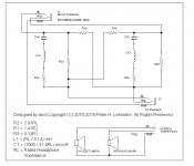
The components of my network correspond to to the rated headphone impedance of the headphones that are to be used with it. See the attached figure. This is important, the network works properly only with headphones of a rated impedance that the network has been built for.
As the network is made up of only six 1/2W resistors, two non-polarized capacitors, and two inductors, this is fairly easy to try. However inductance of the inductor can become fairly substantial for higher rated headphone impedance. So this will be easier to try for lower rated impedance; inductor L1 equals 1 mH where the network is built for 32 Ohm rated impedance. The commercial coils intended for speaker system cross-over networks can be used in my network. The actual component values can be standard values as close as possible to the calculated values. DCR of the inductors can be up to but not more than the resistance of R3
Inserting the network between amplifier and headphones lowers volume somewhat, but unless you are already using a high volume control setting of the amplifier driving your headphones, most likely your current amplifier is adequate to drive your headphones through the network too.
Load presented to the amplifier by headphones connected to the network is never lower than the rated impedance of the headphones.
My design has a strong if unorthodox basis in acoustics. If interested in the derivation of the circuit design, see my article here:
http://www.zen22142.zen.co.uk/Design/Xfeed-Net.pdf
Please try my network and post the results of your listening test to this thread.
Thanks for trying (enjoy it),
Pete
Attachments
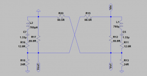
Is this the frequency response you are trying to achieve ?
File is LT Spice schematics.
Patrick
You can see the frequency response (FR) of my network in the form of a table if you view my article that I provide a link to in my first post. The FR is what I obtained by a computer simulation, but is quite close to what you would get from the actual network. I don't have LT Spice, so I'm not able to look at that FR that you provide.
Regards,
Pete
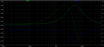
In PNG for your convenience.
Patrick
Yes, the solid green and blue traces. The green dashed line is phase is that correct? Measured relative to what?
Note that what I sought to emulate is the dB difference of the sound at the far ear relative to that at the near ear. If you compare sound level versus frequency at the near ear to direct phone reproduction, and sound level versus frequency at the far ear to cross phone reproduction, both separately, there is much less correspondence.
Thanks for the interest,
Pete
Peter - any connection to Lehmann Audio ?
Lehmann Audio is not me. That is quite a coincidence, though. I was surprised to see that name in one of threads at this forum. Is there a Lehmann Audio website?
Regards,
Pete
Lehmann Audio is not me. That is quite a coincidence, though. I was surprised to see that name in one of threads at this forum. Is there a Lehmann Audio website?
Regards,
Pete
https://www.lehmannaudio.com/
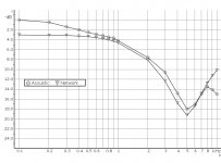
Since Patrick brings up the issue of frequency response, I am attaching a graph of frequency response of my network compared to acoustic frequency response.
This graph shows a very particular type of frequency response comparison. The acoustic response of the graph is typical sound intensity at the far ear relative to that at the near ear for a sound source located in front of the listener at a 45 degree angle horizontally relative to directly in front (azimuth). The network response of the graph is electrical power given to the cross-feed headphone relative to that given to the direct headphone.
These responses will look unusual because they take into account gain effected by parts of the near outer ear that is at a maximum for a sound source located off to one side at a 45 degree angle frontally. Wearing headphones I am assuming will largely defeat gain of the outer ear.
All of this will be made more understandable by reading my article here
http://www.zen22142.zen.co.uk/Design/Xfeed-Net.pdf
Attachments
Last edited:
Headphones are already designed to account for HRTF. Your crossfeed's output (mix of the EQ'd and delayed L, R signals) should have fairly flat frequency response.
Also I see no mention of ITD (interaural time delay) at all, but it's crucial to get right for the whole bass and mids range. It's also uncommon for your ILD (level difference) to decrease so strongly above 5 kHz. The pinna and ear canal still have a strong influence in the far ear, which you seem to ignore?
Also I see no mention of ITD (interaural time delay) at all, but it's crucial to get right for the whole bass and mids range. It's also uncommon for your ILD (level difference) to decrease so strongly above 5 kHz. The pinna and ear canal still have a strong influence in the far ear, which you seem to ignore?
Last edited:
Headphones are already designed to account for HRTF. Your crossfeed's output (mix of the EQ'd and delayed L, R signals) should have fairly flat frequency response.
Also I see no mention of ITD (interaural time delay) at all, but it's crucial to get right for the whole bass and mids range. It's also uncommon for your ILD (level difference) to decrease so strongly above 5 kHz. The pinna and ear canal still have a strong influence in the far ear, which you seem to ignore?
Most headphones as far as know are designed to deliver a flat frequency response separately to each ear. Can you name a type of headphones that has built-in cross-feed and/ or produces a peak in response at 5 kHz?
If you are referring to the frequency response graph in my previous post, that curve shows level at the far ear with respect to level at the near ear. For example, if the headphones get only the left channel signal, then the level of the cross-feed to the right channel headphone relative to the level given to the left (direct) headphone. For frequency > 5 kHz and increasing, the typical acoustic level at the far ear relative to that at the near ear, that I sought to mimic as closely as possible, initially increases as resonance of the concha very rapidly decreases and then starts decreasing again due to the sound shadow.
The concha and flange produce maximum gain when a source is at a 45 degree angle horizontally (to the side). At the far ear, the head is getting in the way.
Definitely I only focused on ILD and neglected ITD. In a passive circuit, I wouldn't know how to accomplish the correct ITD, especially designing a simple network, which was one of my design goals.
Regards,
Pete
Not really. Almost all of them produce e.g. a 10 dB boost at roughly 3 kHz. As I said, they incorporate HRTFs in the form of equalization curves (I'm sure you've heard of diffuse field, free field ..) and the rest is due to the designer not caring, reaching the limits of mechanical equalization or deliberate voicing.Most headphones as far as know are designed to deliver a flat frequency response separately to each ear.
Of course headphones do not have crossfeed built in. The only thing that comes remotely close is something like the K1000.
I understand that. I've developed such stuff.If you are referring to the frequency response graph in my previous post, that curve shows level at the far ear with respect to level at the near ear. For example, if the headphones get only the left channel signal, then the level of the cross-feed to the right channel headphone relative to the level given to the left (direct) headphone.
What I was saying is that your output (the mix) would need an extra EQ to counter what your circuit is doing to the frequency response to not sound bad with most headphones. If your headphone needs a boost at 5 kHz then it could work however.
I don't know what you're trying to say. It seems your sentence is missing a few words?For frequency > 5 kHz and increasing, the typical acoustic level at the far ear relative to that at the near ear, that I sought to mimic as closely as possible, initially increases as resonance of the concha very rapidly decreases and then starts decreasing again due to the sound shadow.
The head shadow is what attenuates high frequencies stronger at the far ear, yes, but that doesn't change anything about the ear canal resonance and concha, pinna, ... still having a significant influence.
Also, ILD starts to become significance for our hearing already at ~2 kHz, not 5.
So I'm still wondering why you chose those filters. They don't match HRTFs.
The first step is to calculate the delays involved. With the right filters you can get very close to desirable values even in a passive circuit, but I strongly doubt that the filters and values you chose would come close to that.Definitely I only focused on ILD and neglected ITD. In a passive circuit, I wouldn't know how to accomplish the correct ITD, especially designing a simple network, which was one of my design goals.
Last edited:
Not really. Almost all of them produce e.g. a 10 dB boost at roughly 3 kHz. As I said, they incorporate HRTFs in the form of equalization curves (I'm sure you've heard of diffuse field, free field ..) and the rest is due to the designer not caring, reaching the limits of mechanical equalization or deliberate voicing.
What aspect of HRTF does the boost at 3 kHz correspond to?
The point is that for a 45 degree azimuth to the left in front, then mostly the concha (cave) and to a lesser extent the flange of the left ear only produces about a 9 dB increase of level at 5 kHz. Think about the fact that the ears are located on opposite sides of the head. Also the openings to the ear canal of each ear are at a 180 degree angle. If the sound is coming from 45 degrees to the left of the listener, then it's impossible for that sound to enter the right ear at the same angle as it is in the left ear. Entering the ear at a 45 degree angle, where the sound source is located to the left of the left ear, or to the right of the right ear results in maximum gain. At other angles, the gain is diminished.I don't know what you're trying to say. It seems your sentence is missing a few words?
The head shadow is what attenuates high frequencies stronger at the far ear, yes, but that doesn't change anything about the ear canal resonance and concha, pinna, ... still having a significant influence.
Also, ILD starts to become significance for our hearing already at ~2 kHz, not 5.
So I'm still wondering why you chose those filters. They don't match HRTFs.
Do you consider the affect of the sound shadow in the high frequency range on relative level at the near ear relative to that at the far ear to be a HRTF? The processing of my network mimics the sound shadow, and gain by the concha and flange.
-Pete
Last edited:
typo in article
By the way, in my article explaining this design,
http://www.Zen22142.Zen.co.uk/Design/Xfeed-Net.pdf
there is a typo in the heading of Column 3 of the article's table. It should read "decibels of Column 2 minus decibels of Column 1".
By the way, in my article explaining this design,
http://www.Zen22142.Zen.co.uk/Design/Xfeed-Net.pdf
there is a typo in the heading of Column 3 of the article's table. It should read "decibels of Column 2 minus decibels of Column 1".
Last edited:
Xfeed network for Koss KSC75
Earlier this week I built a network according to my design for the Koss KSC75 headphones. Rated impedance of the KSC75 is 60 Ohm. That means that inductor L1 in my network equals 1.9 mH. Using commercial inductors for speaker cross-overs with 18 AWG enameled wire would take up quite a lot of space, so I scramble-wound 28 AWG enameled wire on iron cores removed from 2 commercial coils. Each coil needed 36 feet of wire, which is not too bad to wind by hand.
Using iron core inductors, the result is a much less bulky piece of equipment. See the attached photo. As I mention in my article, it is necessary to separate the two coils by at least 8 cm, and orient them at a right angle. That means that the network takes more space, but it is then still not too bulky. The penalty for not eliminating interaction between the coils is unintended cross-feed.
The combination of the KSC75 and my network results in great reproduction. By the way, the Koss KSC75 headphones are excellent, and especially excellent relative to the going price for them.
Regards,
Pete
Attachments

- Status
- Not open for further replies.
- Home
- Amplifiers
- Headphone Systems
- my probably new cross-feed