Hi guys!
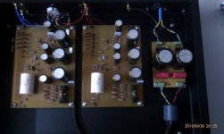
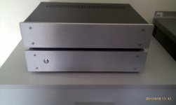
This is my first post and I would like to show my Pearl One :
https://picasaweb.google.com/115042429352783535448/PearlPass#5665708755140994
https://picasaweb.google.com/115042429352783535448
I have some questions and I want to know if anyone can help me.
At the output of the power supply, I check about 48 volts DC, is this value is correct? This voltage is it safe for the circuit?. I'm using basically the scheme of the unregulated supply (Pearl One PDF page 3, Fig 4):
A pair of Diodes 2KBP01M, capacitors (Nichicon Gold Tune, 10.000 uF), and a pair of Wima MKS4.
My R-core have an output of 30 volt but when I checked, the output have 34 volt AC.
Thanks and regards
Attachments
 )
)
Hi guys!
This is my first post and I would like to show my Pearl One :
https://picasaweb.google.com/115042429352783535448/PearlPass#5665708755140994
https://picasaweb.google.com/115042429352783535448
I have some questions and I want to know if anyone can help me.
At the output of the power supply, I check about 48 volts DC, is this value is correct? This voltage is it safe for the circuit?. I'm using basically the scheme of the unregulated supply (Pearl One PDF page 3, Fig 4):
A pair of Diodes 2KBP01M, capacitors (Nichicon Gold Tune, 10.000 uF), and a pair of Wima MKS4.
My R-core have an output of 30 volt but when I checked, the output have 34 volt AC.
Thanks and regards
Hi Blackdod,
If your Pearl works fine there is nothing to worry about 🙂
More technically, all depends which voltage value you get after the regulation. An input of 45-46V is quite correct before reg, so your value seems fine at a first glance.
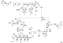
Better check voltage onboard, e.g. for example between Q1 drain and ground you should measure 29V or so. If not, the discrete regulator is likely to have a problem and you'll have to debug this 🙂
Best,
nAr
Last edited:
Hey guys
Thanks for your answers.
Right now I'm thinking of remaking the selector to make it look a little more professional.
Today I will do my first listen to the final assembly... I hope not to have any problems.
Regards
Thanks for your answers.
Right now I'm thinking of remaking the selector to make it look a little more professional.
Today I will do my first listen to the final assembly... I hope not to have any problems.
Regards
Nice. But don't link too big images, they change the reading frame and are difficult to some. I made those to attachments so they never get lost as expired links even. Also, other guys don't quote along with same images if in same page. Thanks. 
Nice. But don't link too big images, they change the reading frame and are difficult to some. I made those to attachments so they never get lost as expired links even. Also, other guys don't quote along with same images if in same page. Thanks.
Sorry Salas
Thanks and regards
Hi Guys
After a few hours, I have the same problem on both plates . I heard a noise and saw that the IRF9510 was burned. I've replaced and now I have +29.5 volt regulated again after the R8. Until this point everything well.
The problem I see now is that the R17 (14 volt) and R14 (19,5 volt) I have a voltage of 29 volts!
On the other hand, in the C7, I have a value of 26 volts (I assume that this value can be considered normal), but in the C8, I checked 29 volt again.
Is it possible that ZTX450 are wrong? I do not understand how the scheme after the R14 indicates a value of 19 volt and 29 volt I always check here.
Any ideas??
Thanks
Hi
The data that I could check. They are all on PAD2 - (pin negative)
Regards
The data that I could check. They are all on PAD2 - (pin negative)
An externally hosted image should be here but it was not working when we last tested it.
Regards
Sorry I can´t "upload" any file. (Why? )
The link of my dates:
https://picasaweb.google.com/115042429352783535448/PearlPass#5667874825768721666
Regards
The link of my dates:
https://picasaweb.google.com/115042429352783535448/PearlPass#5667874825768721666
Regards
Hello
I'm thinking of changing ZTX450 for BC337-40 while I expect a new shipment of ZTR450 from Mouser. Logically, I would have put the BC337-40 in the opposite direction ZTX450.
You think it's a good change?
Regards
I'm thinking of changing ZTX450 for BC337-40 while I expect a new shipment of ZTR450 from Mouser. Logically, I would have put the BC337-40 in the opposite direction ZTX450.
You think it's a good change?
Regards
Hello
I'm thinking of changing ZTX450 for BC337-40 while I expect a new shipment of ZTR450 from Mouser. Logically, I would have put the BC337-40 in the opposite direction ZTX450.
You think it's a good change?
Regards
Q3 and Q4 seems not to have supported the excessive V+ before reg. was working. Maybe 337_40 will work, but I dunno if the excess hfe would not be troublesome in the subregulator (Q3). BC550C would work fine in all those places I assume.
I hope your matched jfets and the K389 are still good. Check if you have a voltage on R25 and all source Rs of the first stage. Beware of pinout for BCs, check before soldering. Might be 180° reversed 🙂
Best,
nAr
The voltage across to R25 is relative to pin negative or ground?
Relative to negative, I checked 25 volt 🙁 🙁 if it´s relavive to ground, 0 volt.
Regards
Relative to negative, I checked 25 volt 🙁 🙁 if it´s relavive to ground, 0 volt.
Regards
Last edited:
The voltage across to R25 is relative to pin negative or ground?
Relative to negative, I checked 25 volt 🙁 🙁 if it´s relavive to ground, 0 volt.
Regards
Voltage indication 0,05V states a measurement taken between [point: sources nodes of double jfet and R25] and Ground.
it's about 50mV, a fairly low value. To be accurate, your DVM scale must be set in the 200 mV full range.
Ohm law gives I=U/R or 5mA in the branch. That means each jfet in the 2SK takes about 2,5 mA.
If you don't have any V at all across this R, that means current does not flow.
So, check if the cascode Q4 has now good V values as per schematic. If yes, and no correct V on R25, then the 2SK389 might be broken.
If not, e.g. no correct values around Q4, then Q4 may be broken and has to be changed.
Perhaps after Q4 changed, and correct values around, and still no V on R25 ? try to change the 2SK389.
Also be sure to verify that you get about 13,4V on the jfet drains (referenced to Ground)
Best,
nAr
Thanks Nar
I believe that the Q4 it´s broken because I don´t have any correct values around Q4 and Q3
Today I will be working with a couple of hours to see if I have a correct voltage area Q4.
I'm thinking that possibly the SK39 that I have are wrong , but until I get to fix the problems in the area of Q4 and Q3 will not change.
I'll tell you.
I believe that the Q4 it´s broken because I don´t have any correct values around Q4 and Q3
Today I will be working with a couple of hours to see if I have a correct voltage area Q4.
I'm thinking that possibly the SK39 that I have are wrong
, but until I get to fix the problems in the area of Q4 and Q3 will not change.I'll tell you.
I'm thinking that possibly the SK39 that I have are wrong
I'll tell you.
Where did you buy the k389s ? Some probability to have fake batchs on internet nowadays. Also, GR types will work fine, don't bother find BLs they are not needed
Best,
nAr
Hello
I changed the ZTX450 for BC337-40, but the results have really been the same. I keep getting in the wrong voltage of Q3 and Q4. If I measure with respect to ground I get a few millivolts while if I measure with respect to pin negative still have voltages on the order of the 29 volts. 😡
I hope that with the new ZTX450 I will get better results. 😕
As for the SR389, I bought some online and others in my local distibuidor (physical store), but I did not so clear that I have are original.😕
The voltage that I have now, before of the R25 is about 10 mVolt (with respect to ground), but still, I think the problem comes from the area of Q4 ... but this is something I can only guess.
Regards
Hello
I changed the ZTX450 for BC337-40, but the results have really been the same. I keep getting in the wrong voltage of Q3 and Q4. If I measure with respect to ground I get a few millivolts while if I measure with respect to pin negative still have voltages on the order of the 29 volts. 😡
I hope that with the new ZTX450 I will get better results. 😕
As for the SR389, I bought some online and others in my local distibuidor (physical store), but I did not so clear that I have are original.😕
The voltage that I have now, before of the R25 is about 10 mVolt (with respect to ground), but still, I think the problem comes from the area of Q4 ... but this is something I can only guess.
Regards
Make sure regulator works fine first.
I assume you know on Pearl PSU is not symmetrical, so pin negative and GND are the same ... it's ground reference, hence 0V.
Check bipolars pinout and orientation.
For example, ZTX 450 and BC550C have their pins reversed, e.g. if you use BC550C instead of ZTX 450 you must mount them 180° reversed referenced to silkscreen transistor print ...
10 mV on R25 means intended current does not flow correctly. You should have about 50 mV ...
Hope this helps,
Best
nAr
- Status
- Not open for further replies.
- Home
- Amplifiers
- Pass Labs
- My Pearl One. Some questions