Very interesting! As one who uses Wharfedale W15s in about 250L boxes with Gilbert Briggs distributed port concept, and driven by their own amplifiers from an active crossover, and thoroughly enjoys the bass response, the original comments and design should have given first class results.
In the final analysis, one listens to the music, and if the music sounds OK then its a great system.
In the final analysis, one listens to the music, and if the music sounds OK then its a great system.
I think what I've learned here has shown me what I should do with the speaker systems.
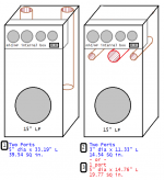
1. Cerwin Vega V152D woofers. These are rated 500W. Not going to worry about a 1dB hump in the 30-40Hz lower bass. Going to hope to see it at -1dB at 20Hz, and -3 at 17Hz. That curve may not even manifest the same when the job's done. As long as it's close.
2. Port the boxes. This is one thing that was probably missing before. I presume that the more area per tuned port, the less chuff there will be. There may be several good choices for ports, depending on pipe sizes available. I should look into purpose-made ports too, but PVC is everywhere.
Port O.D. and I.D. for common schedule 40 & 80 PVC pipe sizes (all inches)
size_____OD________ID________#ports_____port L____sched.___sq. in. area
4________4.500_____3.786_____1___________7.73_____80______11.26
4________4.500_____3.998_____1___________8.78_____40______12.56
3________3.500_____3.042_____2__________11.33_____40______14.54
5________5.563_____5.016_____1__________14.76_____40______19.77
4________4.500_____3.786_____2__________18.23_____80______22.52
4________4.500_____3.998_____2__________20.49_____40______25.12
6________6.625_____5.709_____1__________19.70_____80______25.61
6________6.625_____6.031_____1__________22.23_____40______28.58
5________5.563_____5.016_____2__________33.19_____40______39.54
The cabinet inside, front to back, is 16.5 inches, so I assume I need at least one half a port diameter's space between the end of the port and the back wall of the cabinet?
Can the ports be used with a 90 degree section of pipe to turn them so they don't hit the rear wall?
If so, what will that do to the tuning? I mean, the distance along the inside of the pipe has a short radius and a long radius.
Instead of front to back, can the port go sideways across the width dimension, or vertically exiting at the bottom?
Is there a rule for port location distance from the driver?
Thanks in advance for your advice!
Last edited:
That book with the 20Hz figure, believe it or not is Radio Shack "Building Speaker Enclosures" 2nd edition 1984, cat no. 62-2309. It's actually a rebranded TAB book by David Weems.
I don't know what is meant by modest power. Acoustic or electrical? I think the 15" in there was doing all it could, but would benefit by a port to tune the box. It's done for now, new drivers have to be bought.
"Acoustic Design Charts" by Frank Massa 1942. It's on archive.org.
so much for the sensitivity on that Eminense/MCM speaker being 93dB@1M @1W. Or there could be a decimal off somewhere in my work or even the online calc since dynes/cm^2 conversion to dB SPL requires a reference level based on human hearing.
I assumed it was one of DW's [I have the TAB version. 😉]
Thanks! Frank Massa, now there's an audio great! Right up there with Olson, Lansing, Hilliard, Shearer, et al, that's largely unknown on the forums.
Modest electrical power, i.e. stays well within its Xmax rating, With most drivers, just see a little movement. Some folks say 10% of driver rated power, but with many modern drivers the ratings are just so much floobie dust, so caveat emptor applies.
Accurately calculate driver efficiency:
n0 = 9.6352*10^-10*Fs'^3*Vas(liters)/Qes'
SPL = 112.018+10*Log(n0)
Qes' = Qes + any added series resistance [Rs]: HiFi Loudspeaker Design
GM
I learned about multiple ports - -they are like an inductor, put them in parallel and the value (length) goes down.
Here's a WinISD project using the Cerwin Vega 15" sub -it has two 2-Ohm coils and Fs 19Hz, Xmax 24mm. There is a port, 5", tuned as shown.
When paralleling ducted ports the length of each increases with increasing number of ports due to increasing friction losses. Bjorno's vent design 'cheat sheet': https://www.diyaudio.com/forums/att...rt-slot-port-math-effective-port-length-1-jpg
FWIW, HR sims a ~2.8 dB peak and the single 5" vent can handle your 850 W down to ~25 Hz where vent mach goes ballistic, requiring a TL length 400 cm^2 vent if trying to reproduce some pipe organ and movie LFE soundtracks.
GM
1. Cerwin Vega V152D woofers. These are rated 500W. Not going to worry about a 1dB hump in the 30-40Hz lower bass. Going to hope to see it at -1dB at 20Hz, and -3 at 17Hz. That curve may not even manifest the same when the job's done. As long as it's close.
2. Port the boxes. This is one thing that was probably missing before. I presume that the more area per tuned port, the less chuff there will be. There may be several good choices for ports, depending on pipe sizes available. I should look into purpose-made ports too, but PVC is everywhere.
The cabinet inside, front to back, is 16.5 inches, so I assume I need at least one half a port diameter's space between the end of the port and the back wall of the cabinet?
Can the ports be used with a 90 degree section of pipe to turn them so they don't hit the rear wall?
If so, what will that do to the tuning? I mean, the distance along the inside of the pipe has a short radius and a long radius.
Instead of front to back, can the port go sideways across the width dimension, or vertically exiting at the bottom?
Is there a rule for port location distance from the driver?
Thanks in advance for your advice!
1. FWIW, HR sims an ~85.96 dB eff., which falls off to this @ ~19 Hz, ~ -1.1 dB/17 Hz.
2. Correct. Note that woofers can be tuned ~1/2 octave below Fs or ~13.85 Hz based on published Fs, so if tuned this low it will knock down the peaking and push group delay [GD] down low enough for the 5" vent to be OK down to ~16 Hz @ 500 W.
Note too that vents > a few inches long ideally need to be supported.
Don't recall ever seeing any rigorous testing done to find the vent, parallel wall minimum, but a bare pipe's end correction is 0.613*r, so 1r should be OK, though if multiples are used, then it would be the sum of them all unless widely spaced.
Yes, though each bend introduces more losses, hence need to be longer and normally manually tuned if more than one bend if you want a high degree of accuracy [most are indifferent], so space permitting, better to use two 45s and a short straight piece.
Yes to both.
The pioneers concluded that it couldn't be too close, so included a driver-in-vent design in the original reflex patent. This assumes that the cab will have a ~uniform particle density, but due to yours having a high aspect ratio with its attendant 1/4 WL eigenmodes, it would ideally be at the opposite end from the driver where it would be damped by them. With it down near the driver, bottom to get some floor loading there will instead be a 1/2 WL notch in the response.
GM
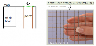
How about #1 in the drawing here? Is that what you are suggesting?
That's as far to the opposite end from the driver as it can be, and has plenty of area.
The only issue might be objects going/falling down the tubes.. Is some stiff, welded 5/16 hardware cloth a fix for that?
Attachments
Here's where it gets tricky........it's the inside pipe opening that ideally needs to be at an odd harmonic*, ditto driver offset, so ~ right where the other drivers are.
I keep forgetting to ask; what are the inside dimensions [i.d.] and what is the driver centerline offset [i.d.]?
Well, normally it would be finer, such as window screen [recommend pet screen], but bigger screen with a felt/whatever filter works too. The main thing is it must be tightly stretched. Foam plugs are popular, use 30 ppi open cell [fish tank filter].
That said, regardless of where they wind up, long vents often need to be critically damped due to its 1/2 WL organ pipe modes 'coloring' the sound: Click Test | GM210 | Flickr
*L x ~ 0.21, 0.349, 0.424, 0.7, 0.848 [most common] normally measured from top [i.d.].
GM
Here's where it gets tricky........it's the inside pipe opening that ideally needs to be at an odd harmonic*, ditto driver offset, so ~ right where the other drivers are.
I keep forgetting to ask; what are the inside dimensions [i.d.] and what is the driver centerline offset [i.d.]?
Well, normally it would be finer, such as window screen [recommend pet screen], but bigger screen with a felt/whatever filter works too. The main thing is it must be tightly stretched. Foam plugs are popular, use 30 ppi open cell [fish tank filter].
That said, regardless of where they wind up, long vents often need to be critically damped due to its 1/2 WL organ pipe modes 'coloring' the sound: Click Test | GM210 | Flickr
*L x ~ 0.21, 0.349, 0.424, 0.7, 0.848 [most common] normally measured from top [i.d.].
GM
Forgive me but I do not understand what you are asking about. I'm not fluent in the casual discussion of these things and not familiar with these terms said without reference to exact things that seem unspoken. I can answer about the drawing based on what I think you are asking. If it's wrong, please be very specific for my dumb questions.
it's the inside pipe opening that ideally needs to be at an odd harmonic*, ditto driver offset, so ~ right where the other drivers are.
*L x ~ 0.21, 0.349, 0.424, 0.7, 0.848 [most common] normally measured from top [i.d.].
I do not understand what is being said here.
1: About the inside pipe opening needing to be at an odd harmonic. (odd harmonic of what, and the interior opening area itself, or some positioning of that opening?)
2: ditto driver offset.
3: ~ right where the other drivers are.
4: *L x ~ 0.21,....
The pipes in the proposed drawing, Being 33" long, and the thickness of the cabinet being 0.75", they will extend 32.25" down, and the ends will be 14.25" above the cabinet floor.
If the port walls (5" I.D. of the pipes) are 1.5" from the inside rear corners, the center lines of the pipes will be 4" from the inside rear corners.
But I think that does not have to do with what you are telling me or it's the wrong answer.
what are the inside dimensions [i.d.] and what is the driver centerline offset [i.d.]?
inside dimensions ignoring the midrange enclosure:
16.5" deep x 46.5" tall x 22.5" wide.
10 cubic feet after subtracting the volume of the midrange enclosure.
Driver centerline offset?:
Driver centerline is centered horizontaly on the front, 11.25" fron the inside walls.
The 15" driver is about 8" deep. I didn't measure it when I had it out.
Driver center line is very close to 15" from the interior 'floor' of the cabinet.
Thank you,
Patrick
The cabinet can not be disassembled, that is 100% certain. There's no way to change the position of the other drivers so there's no need for me to worry about it. If there are new speakers to be built that would be another story.
Last edited:
You're welcome!
Oh well, took a shot, some folks lurk/'bone up' on the lingo a bit before posting.........
L = longest side length of a cab. The decimals are multipliers to find various points/offsets along dim. L.
High aspect ratio cabs like yours are not reflex [vented], but instead have 1/4 WL [TL] pipe action: Resonances of open air columns
Note that while your cab is closed, implying an open cylinder WRT its 1/2 WL pipe action, it's technically a closed cylinder when vented, so stick a vent in it [mass load] and you get a 1/4 WL MLTL alignment.
OK, 15"/46.5" = L*0.3226 offset, close to the most common of the optimal offsets [L*0.349], so 'close enough'.
Ideally, the vent's opening in the cab should be at an odd harmonic, so either at the extreme end or an odd harmonic near it: 46.5"*0.848 = 39.43" center of vent offset, so with the driver box in the way, kind of screwed.
I guess if it was mine I'd cut a hole in the upper side back corner to slide the pipe in, leaving at least one pipe diameter at the other end and run a screw through the speaker back into the pipe to anchor it at L*0.424 from the end to keep the pipe from unduly 'drumming' if/when energized and of course using calk or similar to seal it at the side and let the rest hang free.
If you choose to drop it down inside to near the driver it with put a good size notch somewhere in the [mid] bass, though considering how much a room messes with a speaker's LF BW may make it moot in the scheme of things.
Note that how you locate the vent can impact its tuning, so if interested in a specific tuning, then cut the pipe too long and work backwards.
GM
You're welcome!
Oh well, took a shot, some folks lurk/'bone up' on the lingo a bit before posting.........
L = longest side length of a cab. The decimals are multipliers to find various points/offsets along dim. L.
High aspect ratio cabs like yours are not reflex [vented], but instead have 1/4 WL [TL] pipe action: Resonances of open air columns
Note that while your cab is closed, implying an open cylinder WRT its 1/2 WL pipe action, it's technically a closed cylinder when vented, so stick a vent in it [mass load] and you get a 1/4 WL MLTL alignment.
OK, 15"/46.5" = L*0.3226 offset, close to the most common of the optimal offsets [L*0.349], so 'close enough'.
Ideally, the vent's opening in the cab should be at an odd harmonic, so either at the extreme end or an odd harmonic near it: 46.5"*0.848 = 39.43" center of vent offset, so with the driver box in the way, kind of screwed.
I guess if it was mine I'd cut a hole in the upper side back corner to slide the pipe in, leaving at least one pipe diameter at the other end and run a screw through the speaker back into the pipe to anchor it at L*0.424 from the end to keep the pipe from unduly 'drumming' if/when energized and of course using calk or similar to seal it at the side and let the rest hang free.
If you choose to drop it down inside to near the driver it with put a good size notch somewhere in the [mid] bass, though considering how much a room messes with a speaker's LF BW may make it moot in the scheme of things.
Note that how you locate the vent can impact its tuning, so if interested in a specific tuning, then cut the pipe too long and work backwards.
GM
upper side back corner like this?
The reason is to have the internal pipe opening as far from the speaker as possible?
Pipe going in from the side in conjunction with "anchor it at L*0.424" does not make to me sense because the cabinet width is not the longest dimension and L*0.424" is 19.7" which is wider than the cabinet, so a pipe going in from the side can't be anchored there.
Can you draw what you are saying , just use the paint program on the attachment?
Like what?
Yes.
Length of vent pipe at 0.424 offset from inside end. Acoustically, the vent is an open pipe [see previous link], i.e. like a plucked string, so want to anchor it such that its harmonics are damped somewhat.
Since the vent will extend out the side somewhat there will be some offset where it's secured/sealed to the side plate. Probably won't be optimum since we don't know for sure how long it will be, but should be good enough for a vent.
I don't do drawings.
GM
Ahh well it was late for me and the file didn't get saved. No matter.
I enjoy doing drawings, whether it's 3D stuff for multiphysics modeling, flat schematic/layout, or a quick sketch in paint. Guess it's not for everyone.
Thanks for your help and suggestions. I see now what you mean about the port. Once things move along I can post back with some performance info.
I enjoy doing drawings, whether it's 3D stuff for multiphysics modeling, flat schematic/layout, or a quick sketch in paint. Guess it's not for everyone.
Thanks for your help and suggestions. I see now what you mean about the port. Once things move along I can post back with some performance info.
Got to thinking about the room as well. anyway I need to find the lost microphone for my BSR EQ-3000. It was supposedly a good unit for casual use room checks with white and pink noise, spectrum analyzer included.
- Status
- Not open for further replies.
- Home
- Loudspeakers
- Multi-Way
- My old speakers which were never really right