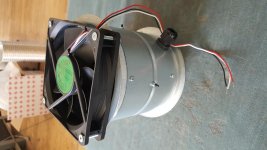
I've just ordered the parts for the chimney. It will be a 125mm ventilation tube with 120mm fan at the top. There should be plenty of room for 4 x 36mm dia caps at the bottom. The main CLCC caps will be in a separate enclosure with the transformers. At nearly £400 for the main caps I don't want them failing early again. Having said that their predecessors have lasted some 10 years even if the amplifier doesn't get used very often. The amplifier only runs at about 50C.
A word of caution. The original caps were NOS so who knows how old they were to start with.
I've got a 16A connector for the umbilical. The Aleph 4 uses about 200W / Channel so 16A capacity should be fine. 48-0-48 rails.
A word of caution. The original caps were NOS so who knows how old they were to start with.
I've got a 16A connector for the umbilical. The Aleph 4 uses about 200W / Channel so 16A capacity should be fine. 48-0-48 rails.
Last edited:
The original PSU was 33000uF 2mH 33000uF 33000uF.
I couldn't quite afford those big caps so it will now be.
22000uF 2mH 22000uF 22000uf ------ 4700uF
The recommended PSU (as published by KK-PCB) was 15000uF 15000uF 1.5mH 15000uF 15000uF. So I am still above his specs.
I couldn't quite afford those big caps so it will now be.
22000uF 2mH 22000uF 22000uf ------ 4700uF
The recommended PSU (as published by KK-PCB) was 15000uF 15000uF 1.5mH 15000uF 15000uF. So I am still above his specs.
Last edited:
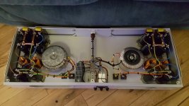
Another benefit is that the finished project won't be so bloody heavy. The dual mono-block was about 55Kg. Just taking the two 625VA transformers out will reduce the weight considerably.
That's the chimney built and ready to install in place of the two transformers.
Attachments
Last edited:
And the 4 x 4700uF final caps.
Mmm the internal photo will not upload. There are 4 x caps inside the chimney.
Mmm the internal photo will not upload. There are 4 x caps inside the chimney.
Last edited:
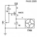
I'm going to design a circuit that starts the fan at 20V and then drops it down to 12V. Easy enough with a PIC.
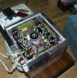
After a lot of saving for new components I'm finally in a position to try and sort out the cooked PSU from dad's old Aleph 4. The new PSU is almost twice the size of the original amplifier. While it is in pieces I'm going to facilitate the balanced input.
Attachments

Last edited:
Pass DIY Addict
Joined 2000
Paid Member
Sure looks like the new PSU will stay cooler than the old one did. Looks like a nice set of components, I'd recommend a nice heavy gauge umbilical cord. I used some three-conductor Neutric connectors for my outboard PSU: Neutrik NAC3MX-W powerCON TRUE1 Male Cable Connector IP65 Rated
I would be inclined to put the caps after the inductor inside the amp to minimise the output impedance of the power supply as well as further remove any noise that might be picked up along the cable (or anywhere else) into the amp etc.
Testing all the components as I remove them I've found that one of the bridge rectifiers has a faulty diode. Odd as they are 35A 200V bridges.
I've got 4 x 4700uF caps in the amplifier casing itself, enclosed in a chimney to keep them cool. The remainder of the PSU is separate.
The PSU ends up being CLCC-C.
Might it be better being CCC-LC ?
The hyphen indicating the umbilical.
Might it be better being CCC-LC ?
The hyphen indicating the umbilical.
The PSU ends up being CLCC-C.
Might it be better being CCC-LC ?
The hyphen indicating the umbilical.
The first option will be better for power supply performance, the second option will be better for longevity of the first cap/s.
The caps before the L see all the ripple current which are large so more caps here reduces the ripple current each cap sees, the caps after the L give you all the performance.
If you bought some more Caps and did CCL-CCC it would be ideal.
- Home
- Amplifiers
- Pass Labs
- My old Aleph 4 clone